
Landfill device for rigid solid waste landfill

A solid waste and landfill technology, which is applied in the fields of solid waste removal, landfill technology, waste collection and transfer, etc. It can solve time-consuming and labor-intensive problems, soil pollution at the burial site, and inability to place solid waste in landfill, etc. question

Active Publication Date: 2022-01-07
HUAIHUA JINYI ENVIRONMENTAL PROTECTION EQUIP
View PDF8 Cites 0 Cited by
  • Summary
  • Abstract
  • Description
  • Claims
  • Application Information

AI Technical Summary

Problems solved by technology

[0007] The technical problem to be solved by this technical solution is: some existing solid waste landfill devices cannot convert some chemical production process The wastes are sorted, isolated, placed and buried, so that the chemical substances remaining on the surface of these fixed wastes with chemical substances on the outer surface will contact and react after the burial, so that the soil field at the burial place is seriously polluted, and the existing fill During the use of the embedding device, the solid waste cannot be neatly placed in the landfill, so that a large irregular pit needs to be dug out during the landfill process, which is time-consuming and laborious

Method used


Image

  • Landfill device for rigid solid waste landfill
  • Landfill device for rigid solid waste landfill
  • Landfill device for rigid solid waste landfill

Examples


Embodiment 1

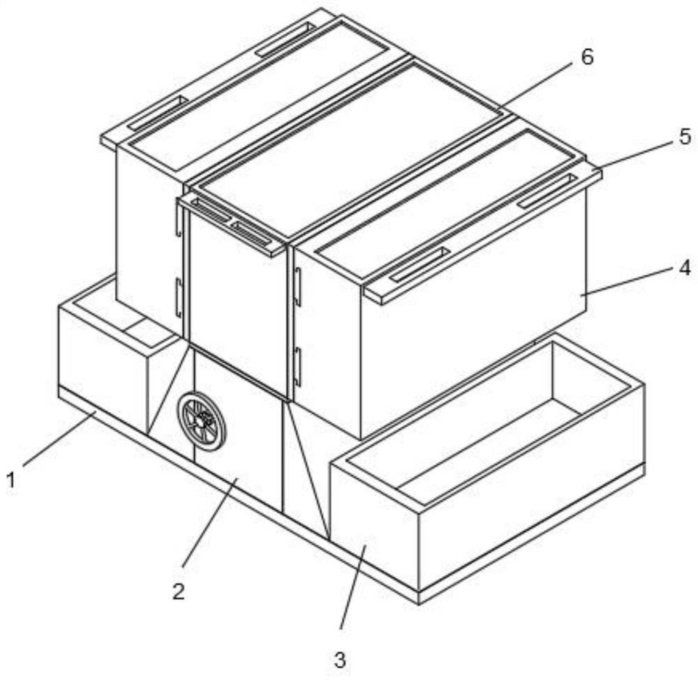
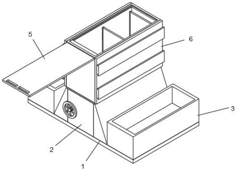
[0040] Such as Figure 1-2 , a solid waste rigid landfill landfill device, comprising a support base 1, an adjustment control device 2, an auxiliary storage frame 3, an auxiliary storage box 4, a sliding sealing plate 5 and a partition storage box 6, the adjustment control device 2 is fixedly connected to the middle part of the upper end of the support base 1, the auxiliary storage frame 3 is distributed on both sides of the adjustment control device 2, and the auxiliary storage frame 3 is fixedly connected to the upper end of the support base 1, and the partition storage box 6 is fixedly connected to the upper end of the adjustment control device 2, the auxiliary storage box 4 is slidably installed on both sides of the separated storage box 6, and the sliding sealing plate 5 is slidably installed on the upper ends of the auxiliary storage box 4 and the separated storage box 6 . The harmful solid waste stained with chemical substances can be separated and isolated by setting ...

Embodiment 2

[0042] Such as image 3 , as a further optimization scheme of the above embodiment: a solid waste rigid landfill landfill device, including a support base plate 1, an adjustment control device 2, an auxiliary storage frame 3, an auxiliary storage box 4, a sliding sealing plate 5 and a partition Place the box 6, the adjustment control device 2 is fixedly connected to the upper middle of the support base plate 1, the auxiliary storage frame 3 is distributed on both sides of the adjustment control device 2, and the auxiliary storage frame 3 is fixedly connected to the support base plate 1, the partition box 6 is fixedly connected to the upper end of the adjustment control device 2, the auxiliary storage box 4 is slidably installed on both sides of the partition box 6, and the sliding sealing plate 5 is slidably installed on the auxiliary storage box. Case 4 and the upper end of case 6 are placed separately. The adjustment control device 2 includes an adjustment control part 7, a...

Embodiment 3

[0044] Such as Figure 4-6 , as a further optimization scheme of the above embodiment: a solid waste rigid landfill landfill device, including a support base plate 1, an adjustment control device 2, an auxiliary storage frame 3, an auxiliary storage box 4, a sliding sealing plate 5 and a partition Place the box 6, the adjustment control device 2 is fixedly connected to the upper middle of the support base plate 1, the auxiliary storage frame 3 is distributed on both sides of the adjustment control device 2, and the auxiliary storage frame 3 is fixedly connected to the support base plate 1, the partition box 6 is fixedly connected to the upper end of the adjustment control device 2, the auxiliary storage box 4 is slidably installed on both sides of the partition box 6, and the sliding sealing plate 5 is slidably installed on the auxiliary storage box. Case 4 and the upper end of case 6 are placed separately. The adjustment control device 2 includes an adjustment control part 7...


PUM


Abstract

The invention relates to the technical field of solid waste filling, in particular to a landfill device for a rigid solid waste landfill. According to the technical scheme, the technical problems that according to an existing device, waste cannot be separately placed, and landfill is inconvenient are solved. The landfill device for the rigid solid waste landfill comprises a supporting bottom plate, an adjusting control device, auxiliary containing frames, auxiliary containing boxes, a sliding sealing plate and a partition placing box, wherein the adjusting control device is fixedly connected to the middle of the upper end of the supporting bottom plate; the auxiliary containing frames are distributed on the two sides of the adjusting control device and fixedly connected to the upper end of the supporting bottom plate; the partition placing box is fixedly connected to the upper end of the adjusting control device; the auxiliary containing boxes are slidably installed on the two sides of the partition placing box; and the sliding sealing plate is slidably installed at the upper ends of the auxiliary containing boxes and the partition placing box. The technical scheme has the beneficial effects that waste needing to be landfilled can be isolated, and the waste can be quickly and conveniently landfilled.

Description

technical field [0001] The invention relates to the technical field of solid waste landfill, in particular to a solid waste rigid landfill landfill device. Background technique [0002] The solid waste rigid landfill landfill device is mainly a device for centralized storage, transportation and burial of solid waste generated in the existing production process. Some existing solid waste landfill devices cannot be used in the process of use. Some wastes produced in the chemical production process are sorted and placed in isolation for landfill, so that the fixed waste with chemical substances on the outer surface will react with the chemical substances remaining on the surface after landfill, so that the soil field at the burial site will be severely damaged. pollution, and the existing landfill devices cannot place solid waste neatly in the landfill during use, so that large irregular pits need to be dug out during the landfill process, which is time-consuming and labor-inte...

Claims


Application Information

Patent Timeline
Patent Type & Authority Applications(China)
IPC IPC(8): B09B1/00B65F1/00B65F1/14
CPCB09B1/00B65F1/0053B65F1/0046B65F1/141Y02W30/10Y02W30/30
Inventor 杨飘
Owner HUAIHUA JINYI ENVIRONMENTAL PROTECTION EQUIP
Learn More