Water injection amount control system for fuel and water injection engine

a technology of amount control system and water injection engine, which is applied in the direction of electrical control, machines/engines, mechanical equipment, etc., can solve the problems of limited natural nox reducing effect and the possibility of flaming out when water is injected too, and achieve the effect of enhancing the nox reducing

Inactive Publication Date: 2000-09-05
MITSUBISHI FUSO TRUCK AND BUS CORPORATION
View PDF13 Cites 162 Cited by
  • Summary
  • Abstract
  • Description
  • Claims
  • Application Information

AI Technical Summary

Benefits of technology

The present invention has been devised based on such point of view and an object thereof is to provide a water injection amount control system for a f

Problems solved by technology

By the way, because the more water is injected, the more the combustion degrades within the cylinder, flameout occurs when water is injected too much.
However, because the related art technology described above has define

Method used


Image

  • Water injection amount control system for fuel and water injection engine
  • Water injection amount control system for fuel and water injection engine
  • Water injection amount control system for fuel and water injection engine

Examples


first embodiment

(a) Description of

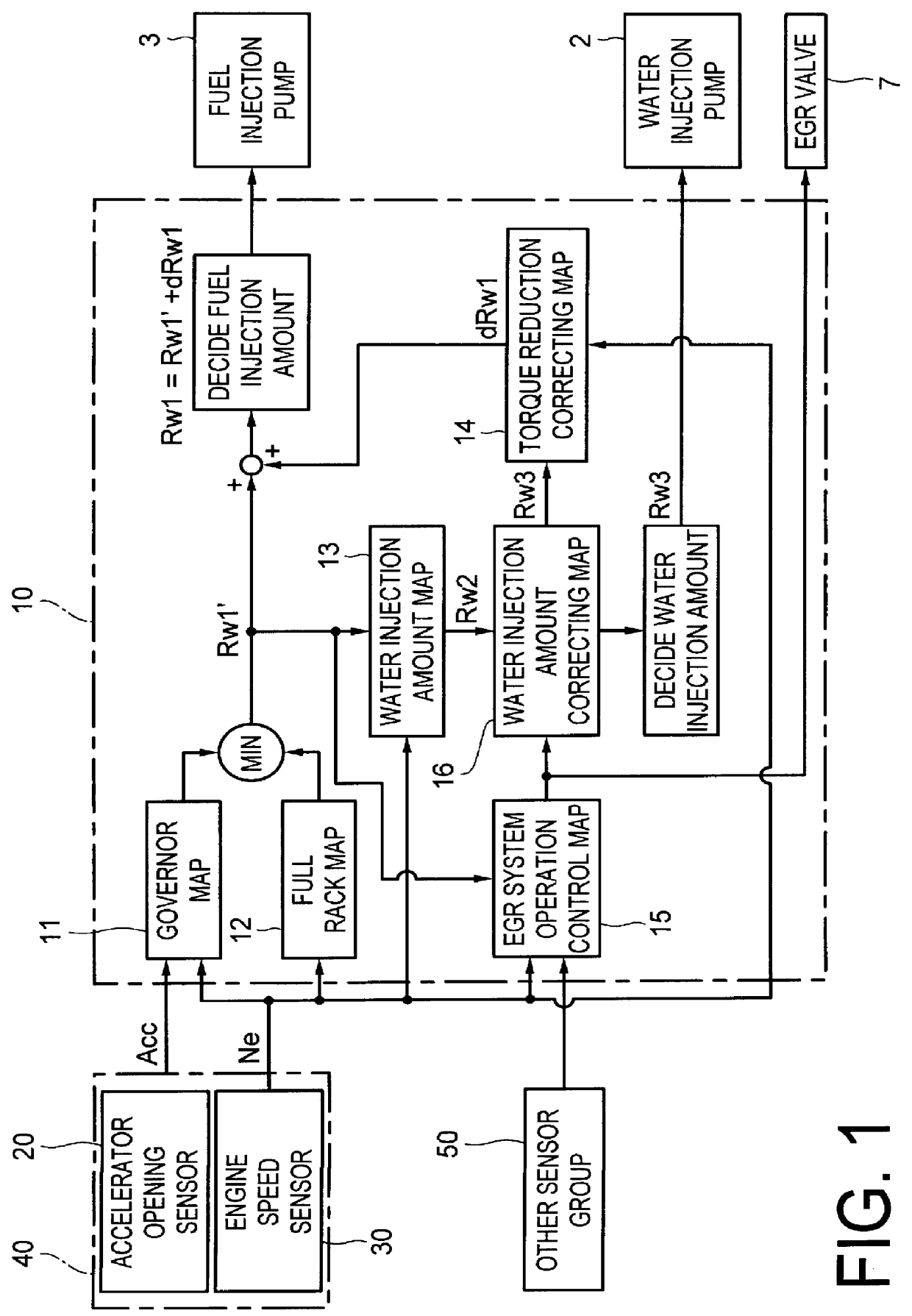
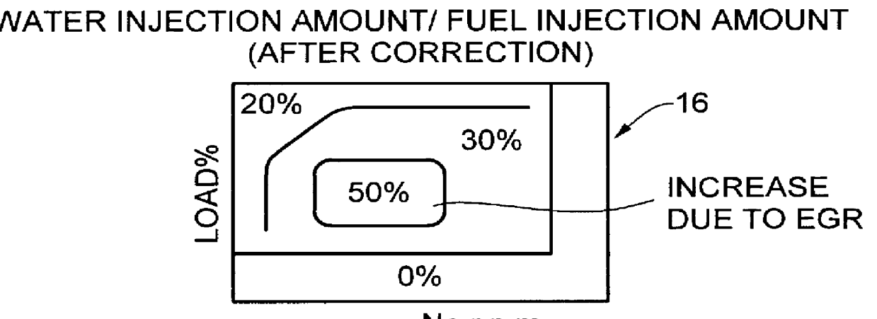
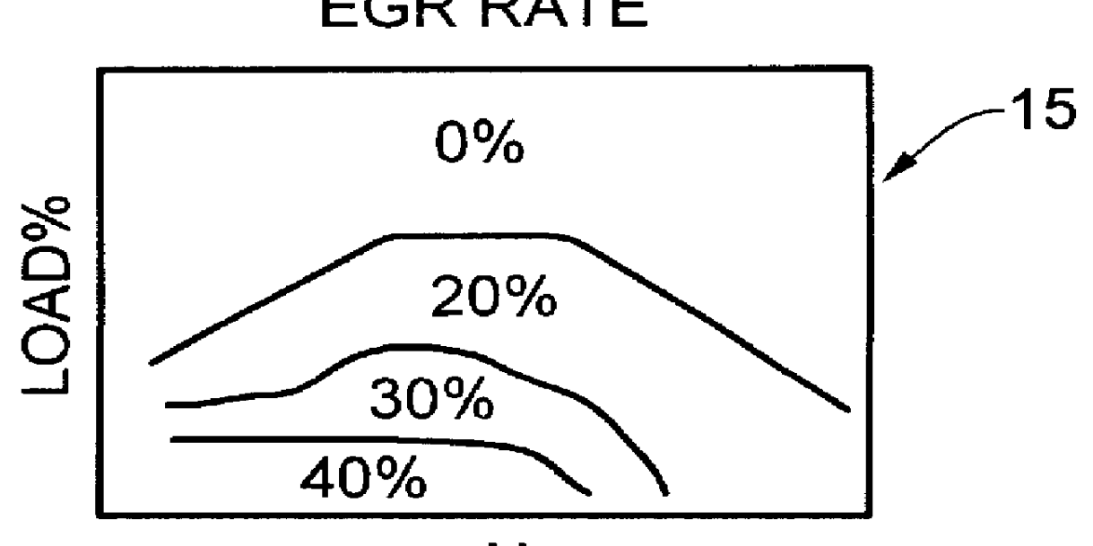
A water injection amount control system for a fuel and water injection engine of the first embodiment of the present invention will be explained at first. FIG. 1 is a schematic block diagram showing the structure of the system by focusing on main functions thereof, FIGS. 2A through 2C are graphs showing the characteristics thereof, FIG. 3 is a schematic diagram showing the entire structure of the engine to which the system of the first embodiment is applied, FIG. 4 is a graph for explaining the characteristic of flameout limit of water injection amount, FIGS. 5A through 5C are graphs for explaining the effects thereof, FIG. 6 is a diagram showing the basic structure of a fuel and water supply system of the fuel and water injection engine, FIG. 7 is a partly enlarged diagrammatic view of an injection nozzle of the fuel and water injection engine, FIG. 8 is a graph for explaining the fuel and water injecting characteristics of the fuel and water injection engine, and...

second embodiment

(b) Description of

The water injection amount control system for the fuel and water injection engine, as the second embodiment of the present invention, will be explained below. FIG. 10 is a schematic block diagram showing the structure thereof by focusing on the main functions thereof, FIGS. 11A through 11E are graphs showing the characteristics of the fuel and water injection engine, FIG. 12 is a schematic diagram showing the entire structure of the engine to which the system of the second embodiment is applied; FIGS. 13A through 13C are graphs for explaining the effects thereof; and FIG. 14 is a graph for explaining a modification thereof.

By the way, although the water injection amount has been corrected corresponding to the EGR rate in the first embodiment described above, the water injection amount is corrected by taking the boost pressure of the turbo-charger 8 as a parameter in addition to the EGR rate in the second embodiment. Beside that, the system of the second embodiment ...


PUM


Abstract

A water injection amount control system for a fuel and water injection engine, comprises running state detecting unit for detecting the running state of the engine; an EGR system for recirculating part of exhaust gas of the engine to a combustion chamber of the engine; EGR system operating state detecting unit for detecting or estimating the operating state of the EGR system; water injection amount regulating unit for regulating an amount of water to be injected to the combustion chamber of the engine; and control unit for controlling the operation of the water injection amount regulating unit: wherein the system is arranged to have water injection amount setting unit for deciding a water injection amount based on information from the running state detecting unit and on the operating state of the EGR system detected by the EGR system operating state detecting unit, so that the control unit controls the operation of the water injection amount regulating unit based on the water injection amount decided by the water injection amount setting unit.

Description

BACKGROUND OF THE INVENTION1. Field of the InventionThe present invention relates to a water injection amount control system for a fuel and water injection engine applied to the engine arranged to inject two fluids of fuel and water to a combustion chamber.2. Description of Related ArtHitherto, various technologies for reducing the discharge of NOx by lowering combustion temperature by injecting water together with fuel into a combustion chamber of an engine have been proposed. For example, Japanese Unexamined Patent Publication No. Hei. 8-226360 has disclosed a fuel and water stratified injection system for injecting in the order of fuel, water, and fuel in stratification from one and same injection nozzle.According to such fuel and water stratified injection system, water is supplied to one and same injection nozzle in advance during the interval period between injections so that fuel, water and fuel are geometrically stratified in this order and the water and fuel are injected to...

Claims


Application Information

Patent Timeline
IPC IPC(8): F02D21/08F02D35/00F02D41/00F02D19/00F02D21/00F02D19/12F02B47/00F02B47/02F02M25/022F02D43/00F02M25/025F02M25/07
CPCF02B47/02F02D19/12F02D21/08F02M25/0227F02M25/03F02M25/0225F02D35/0015F02B29/0406F02M25/0707F02M26/05
Inventor NAKAYAMA, SHINJIMORI, KOJIHAKOZAKI, TAKAZOUSUZUKI, AKIRA
Owner MITSUBISHI FUSO TRUCK AND BUS CORPORATION
Why Eureka
Try Eureka