Optical lens and imaging equipment
An optical lens and lens technology, applied in optics, optical components, instruments, etc., can solve the problems of difficult to match high pixels, high resolution 8M chips, low resolution of vehicle lenses, etc., to achieve improved light flux and good imaging effects. Effect
- Summary
- Abstract
- Description
- Claims
- Application Information
AI Technical Summary
Problems solved by technology
Method used
Image

Examples
no. 1 example
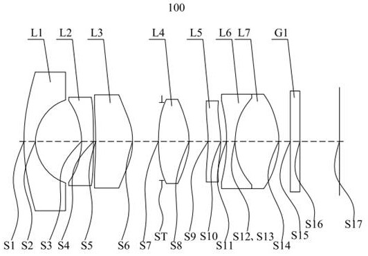
[0071] figure 1 The structural schematic diagram of the optical lens 100 provided for the first embodiment of the present invention, the optical lens 100 includes in sequence from the object side to the imaging surface along the optical axis: a first lens L1, a second lens L2, a third lens L3, and a stop ST , the fourth lens L4, the fifth lens L5, the sixth lens L6, the seventh lens L7, and the filter G1.
[0072] The first lens L1 has a negative refractive power, and its object side S1 is a convex surface, and its image side S2 is a concave surface. Specifically, the first lens L1 is a glass spherical lens;
[0073] The second lens L2 has negative refractive power, and its object side S3 is concave, and its image side S4 is convex, specifically, the second lens L2 is a glass spherical lens;
[0074] The third lens L3 has a positive refractive power, and its object side S5 is concave, and the image side S6 is convex; specifically, the third lens L3 is a glass aspherical lens;...
no. 2 example
[0089] Figure 4 It is a schematic structural diagram of the optical lens 200 provided by the second embodiment of the present invention. The optical lens 200 among the present embodiment is roughly the same as the optical lens 100 among the first embodiment, the difference is that the object side of the third lens L3 of the optical lens 200 in the present embodiment is a convex surface, and the fifth lens L5 is a negative light. Focus, the object side of the sixth lens L6 is convex, and the radius of curvature of each lens is different. For specific parameters of each lens, see Table 2-1.
[0090] The relevant parameters of each lens in the optical lens 200 provided by the second embodiment of the present invention are shown in Table 2-1.
[0091] table 2-1
[0092]
[0093] The surface coefficients of each aspheric surface in the optical lens 200 provided by the second embodiment of the present invention are shown in Table 2-2.
[0094] Table 2-2
[0095]
[0096] ...
no. 3 example
[0100] Figure 7 It is a schematic structural diagram of the optical lens 300 provided by the third embodiment of the present invention. The optical lens 300 among the present embodiment is roughly the same as the optical lens 100 among the first embodiment, the difference is that the object side of the third lens L3 of the optical lens 300 in the present embodiment is a convex surface, and the fifth lens L5 is a negative light. The focal power and the radius of curvature of each lens are different, and the relevant parameters of each lens are shown in Table 3-1.
[0101] The relevant parameters of each lens in the optical lens 300 provided by the third embodiment of the present invention are shown in Table 3-1.
[0102] Table 3-1
[0103]
[0104] The surface coefficients of each aspheric surface in the optical lens 300 provided by the third embodiment of the present invention are shown in Table 3-2.
[0105] Table 3-2
[0106]
[0107] In this embodiment, the field...
PUM
| Property | Measurement | Unit |
|---|---|---|
| Optical length | aaaaa | aaaaa |
Abstract
Description
Claims
Application Information
 - Generate Ideas
- Intellectual Property
- Life Sciences
- Materials
- Tech Scout
- Unparalleled Data Quality
- Higher Quality Content
- 60% Fewer Hallucinations
Browse by: Latest US Patents, China's latest patents, Technical Efficacy Thesaurus, Application Domain, Technology Topic, Popular Technical Reports.
© 2025 PatSnap. All rights reserved.Legal|Privacy policy|Modern Slavery Act Transparency Statement|Sitemap|About US| Contact US: help@patsnap.com