
Wireless charger deployment method based on anisotropy and power limitation

A wireless charger, anisotropic technology, used in current collectors, electric vehicles, electrical components, etc., can solve the problems of charger overheating, battery life reduction, excessive electromagnetic radiation, etc., to achieve high charging safety and practicality Strong and effective effect

Pending Publication Date: 2022-01-07
NANJING UNIV
View PDF0 Cites 0 Cited by
  • Summary
  • Abstract
  • Description
  • Claims
  • Application Information

AI Technical Summary

Problems solved by technology

However, most of the existing studies on directional charging only consider the anisotropy of power and distance, ignoring the anisotropy of power and angle, which leads to a certain degree of energy waste.
[0003] On the other hand, existing research works on wireless charging mainly focus on improving the charging performance while ignoring the adverse effects of overcharging.
In the actual application scenario of wireless charging, overcharging may lead to additional energy loss, reduced battery life, excessive electromagnetic radiation, charger overheating and other adverse effects

Method used


Image

  • Wireless charger deployment method based on anisotropy and power limitation
  • Wireless charger deployment method based on anisotropy and power limitation
  • Wireless charger deployment method based on anisotropy and power limitation

Examples


Embodiment Construction

[0020] In order to better understand the technical content of the present invention, the technical solutions of the present invention will be described below in conjunction with specific embodiments and with reference to the accompanying drawings.

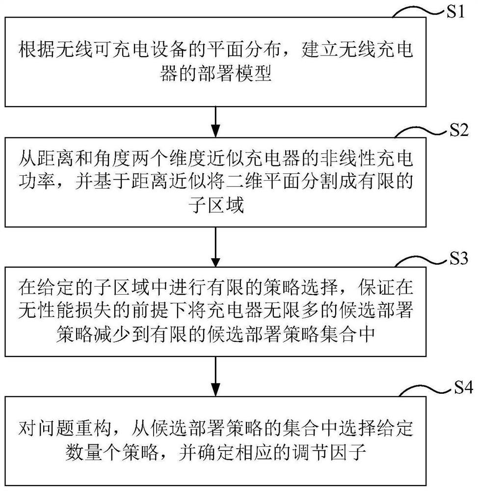
[0021] refer to figure 1 , in an embodiment of the present invention, a wireless charger deployment method is proposed, including the following steps:

[0022] S1, according to the planar distribution of wireless rechargeable devices, establish a deployment model of wireless chargers;

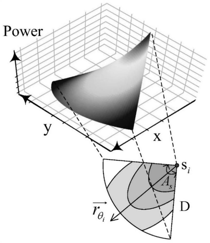
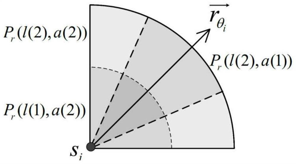
[0023] S2, approximate the nonlinear charging power of the charger from two dimensions of distance and angle, and divide the two-dimensional plane into limited sub-regions based on the idea of ​​distance approximation;

[0024] S3, perform limited strategy selection in a given sub-area, and ensure that the infinitely many candidate deployment strategies of the charger are reduced to a limited set of candidate deployment strategies without performan...


PUM


Abstract

The invention discloses a wireless charger deployment method based on anisotropy and power limitation. The method comprises the following steps of: building a deployment model of a wireless charger according to the plane distribution of wireless chargeable equipment; approximating the nonlinear charging power of the charger from two dimensions, namely distance and angle, and dividing a two-dimensional plane into limited sub-regions based on distance approximation; carrying out limited strategy selection in a given sub-region, and reducing infinite candidate deployment strategies of the charger to a limited candidate deployment strategy set on the premise of ensuring no performance loss; and reconstructing the problem, selecting a given number of strategies from the set of candidate deployment strategies, and determining corresponding regulatory factors. The anisotropic receiving characteristic of the charging power and the overcharging phenomenon of the chargeable equipment are concerned in the charger deployment problem for the first time, and the overall charging effect of a network is effectively optimized while overcharging is avoided through the deployment method.

Description

technical field [0001] The present invention relates to wireless power management, in particular to a wireless charger deployment method. Background technique [0002] Due to its advantages of non-contact, no wiring, and reliable power supply, wireless power transfer (WPT) has attracted extensive attention from industry and academia in recent years. The WPT system consists of a wireless charger and a wireless rechargeable device. In many applications, in order to improve the efficiency of wireless power transfer, the wireless charger is always equipped with a high-gain directional antenna, if and only if the rechargeable device is located in the direction of the wireless charger. The device can only receive effective energy when it is in the charging area. In addition, the charging power received by the device is not only related to the distance between the charger and the device, but also related to the angle between the orientation of the charger and the straight line whe...

Claims


Application Information

Patent Timeline
Patent Type & Authority Applications(China)
IPC IPC(8): H02J50/90H02J50/40H02J7/00
CPCH02J50/90H02J50/40H02J7/00302
Inventor 戴海鹏陈贵海林旭珍
Owner NANJING UNIV
Learn More