Lifting device

A technology of lifting equipment and lifting boards, which is applied in elevators, elevators in buildings, transportation and packaging, etc. It can solve problems such as inconvenient maintenance, no protective structure, and the inability of the bracket to continue to move

Pending Publication Date: 2022-01-11
FICONT IND BEIJING
View PDF11 Cites 1 Cited by
  • Summary
  • Abstract
  • Description
  • Claims
  • Application Information

AI Technical Summary

Problems solved by technology

[0004] Wherein, when the support of the above-mentioned lift is subjected to impact force and moves toward the control switch part, the elastic part provided on the support is prone to jamming, so that the support cannot continue to move, thereby affecting the accurate triggering of the control switch part.
Moreover, since the traction main engine is located outside the roof of the car, there is no protective structure, and maintenance is inconvenient. Special inspection windows need to be installed, and the ventilation of the car is also poor.

Method used


Image

  • Lifting device
  • Lifting device
  • Lifting device

Examples


Embodiment Construction

[0044] Embodiments of the present invention will be further described in detail below in conjunction with the accompanying drawings and examples. The following examples are used to illustrate the present invention, but should not be used to limit the scope of the present invention.

[0045] In the description of the embodiments of the present invention, it should be noted that the terms "center", "longitudinal", "transverse", "upper", "lower", "front", "rear", "left", "right" , "vertical", "horizontal", "top", "bottom", "inner", "outer" and other indicated orientations or positional relationships are based on the orientations or positional relationships shown in the drawings, and are only for the convenience of describing this The embodiments and simplified descriptions of the invention do not indicate or imply that the devices or elements referred to must have a specific orientation, be constructed and operate in a specific orientation, and therefore should not be construed a...


PUM


Abstract

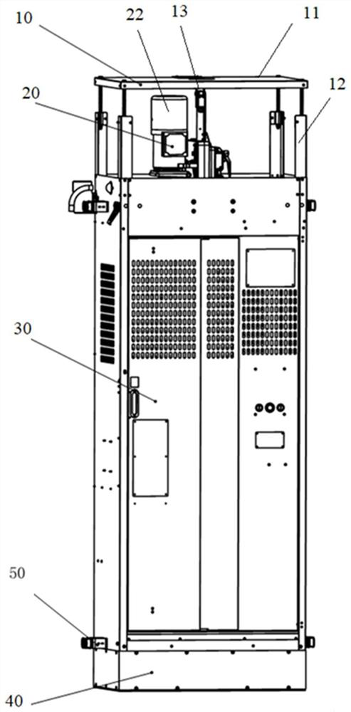
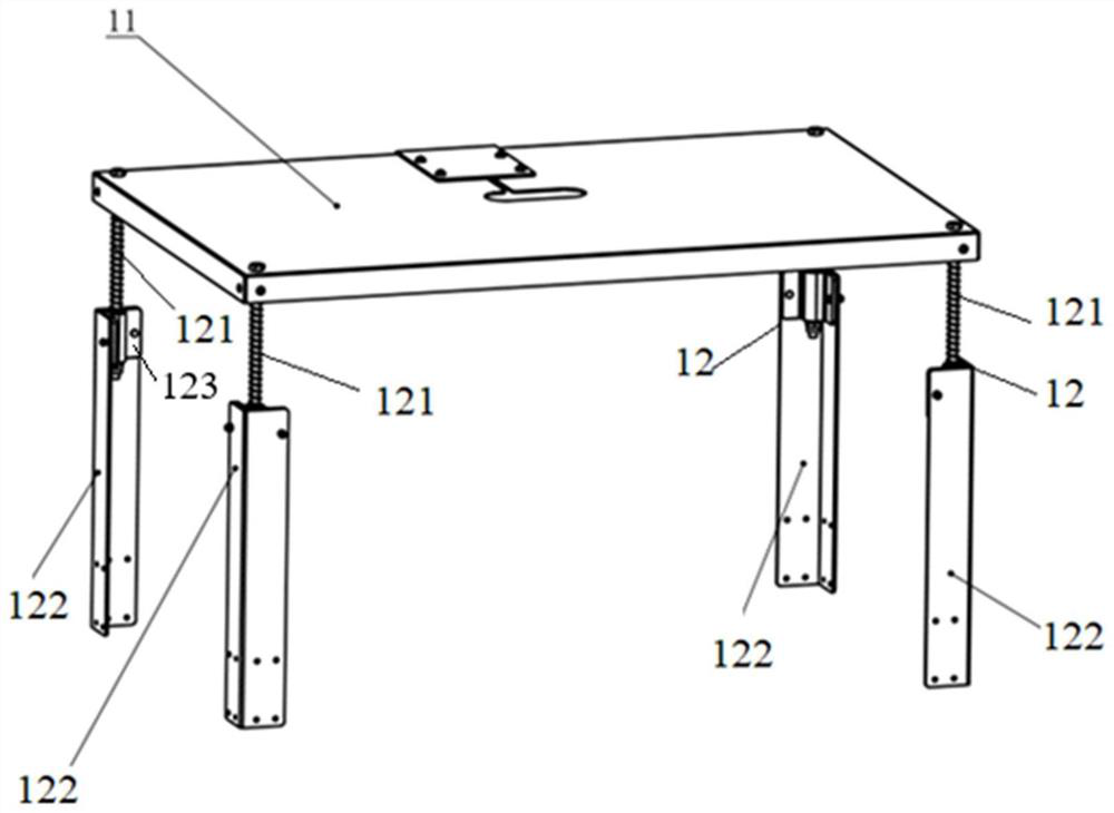
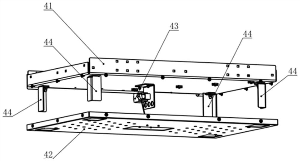
The invention relates to the technical field of high-altitude operation, and provides a lifting device. The lifting device comprises a lift car, a first limiting assembly and a second limiting assembly. The first limiting assembly is located above the lift car and comprises a top plate and a first control switch part, the first control switch part is located between the top plate and the lift car, and the top plate is suitable for moving relative to the first control switch part to trigger the first control switch part. The second limiting assembly is located below the lift car and comprises a third control switch part, and the third control switch part is suitable for being triggered by external force in the downward movement process of the lift car. According to the lifting device, control switch pieces do not need to be installed at a plurality of positions above the lift car correspondingly, the top plate is arranged above the lift car, and the first control switch part is arranged between the upper part of the lift car and the top plate so that the control requirement on the lifting device can be met. In addition, the number of the electric control boxes which are independently arranged in the lift car and correspond to the control switch parts is decreased, and therefore the structure of the lifting device is simplified, and installation and maintenance are convenient.

Description

technical field [0001] The invention relates to the technical field of aerial work, in particular to lifting equipment. Background technique [0002] In order to transport personnel, materials, etc. between the aerial work platform and the initial platform, a lift (lifting equipment) is often used. The hoist is a device that is pulled by a hoist to move up or down along the working wire rope suspended on the lifting point. Among them, the elevator includes a car, an electric control box, a wire rope and ground feet; the elevator is equipped with a traction host, which can ensure that the elevator stops at any position. The electric control box is located inside the car, by controlling the electric control box to control the forward rotation, reverse rotation and stop of the motor, thereby controlling the operation of the elevator. [0003] During the upward and downward process of the existing elevator, in order to make it run to the designated position (generally the init...

Claims


Application Information

Patent Timeline
Patent Type & Authority Applications(China)
IPC IPC(8): B66B1/48B66B11/02B66B11/04
CPCB66B1/48B66B11/0226B66B11/0476B66B11/024
Inventor 王凯旋段晓壮
Owner FICONT IND BEIJING
Why Eureka
Try Eureka