Three-tap type discharge coil differential pressure detection device and method

A discharge coil and detection device technology, which is applied in the direction of measuring devices, measuring current/voltage, measuring electrical variables, etc., can solve the problems of the secondary differential pressure value error and the inability to simulate the operating conditions of the discharge coil, etc.

Pending Publication Date: 2022-01-14
广西电网有限责任公司崇左供电局
View PDF3 Cites 0 Cited by
  • Summary
  • Abstract
  • Description
  • Claims
  • Application Information

AI Technical Summary

Problems solved by technology

Therefore, the conventional test method cannot simulate the actual operating conditions of the discharge coil, and the measured secondary differential pressure value will also have a large error

Method used


Image

  • Three-tap type discharge coil differential pressure detection device and method
  • Three-tap type discharge coil differential pressure detection device and method

Examples


Embodiment 1

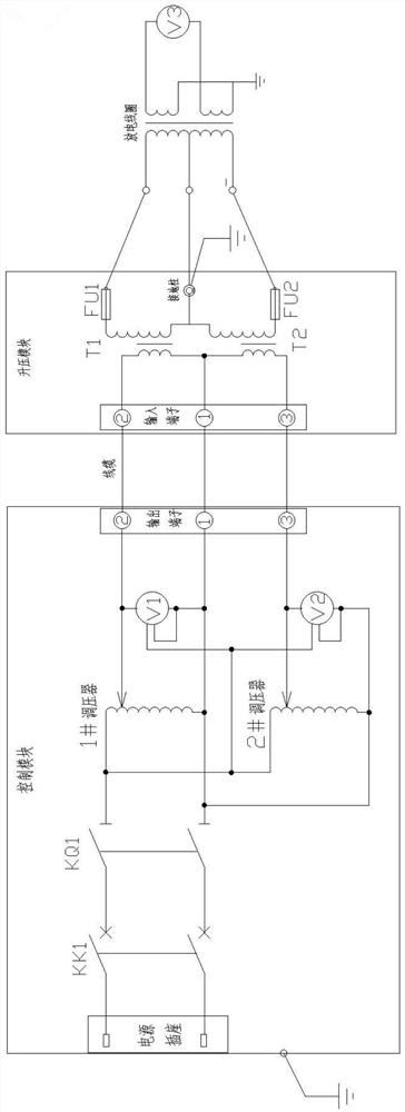
[0023] Such as figure 1 Shown is a three-tap type discharge coil differential pressure detection device, the differential pressure detection device includes a control module, a boost module and a detection module, wherein the control module is connected to an external power supply and the boost module respectively, and the The voltage input by the external power supply is adjusted to the detection voltage of the required ratio and then sent to the booster module for boosting; the booster module is connected to the primary winding of the discharge coil to be detected, and the boosted detection voltage is input for detection; The detection module includes a voltmeter V3, and the two measurement terminals of the voltmeter V3 are used to connect with the secondary winding of the discharge coil to detect the voltage difference of the secondary winding.

[0024] The control module includes a power socket, a leakage protection switch KK1, an isolating switch KQ1, a 1# voltage regulat...

Embodiment 2

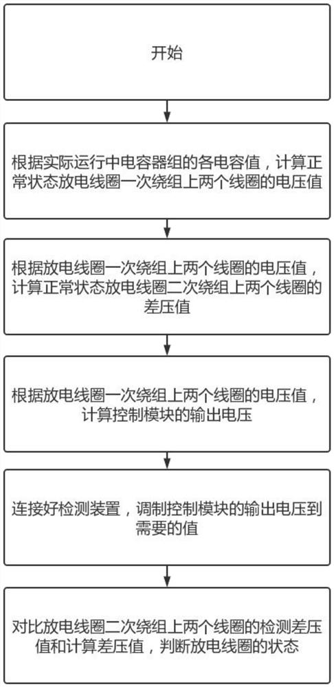
[0031] Such as figure 2 As shown, a three-tap type discharge coil differential pressure detection method, the method is applied to a three-tap type discharge coil differential pressure detection device described in the above implementation, including the following steps:

[0032] S1: According to each capacitance value of the capacitor bank in actual operation, calculate the voltage value of the two coils loaded on the primary winding of the discharge coil in parallel with it in the normal state;

[0033] S2: According to the voltage value of the two coils on the primary winding of the discharge coil, calculate the differential pressure value of the two coils on the secondary winding of the discharge coil;

[0034] S3: According to the voltage value of the two coils on the primary winding of the discharge coil and the boost ratio of the booster T1 and booster T2 in the booster module, calculate the required output voltage of the 1# voltage regulator and the 2# voltage regulat...


PUM


Abstract

The invention provides a three-tap type discharge coil differential pressure detection device and method. The detection device comprises a control module, a boosting module and a detection module. The control module is respectively connected with an external power supply and the boosting module, the boosting module is connected with a primary winding of a three-tap type discharge coil, and the detection module is connected with a secondary winding of the three-tap type discharge coil. According to the method, the voltage values of two coils on a primary winding and the differential voltage value of two coils on a secondary winding of a discharge coil in a normal state are calculated according to a capacitor bank, then the output voltage of a control module is calculated and adjusted, then the detected differential voltage value and the calculated differential voltage value are compared, and the state of the discharge coil is judged. Whether the discharge coil has a fault or not can be simply and quickly judged, the test result is real and credible, whether the performance parameters of the discharge coil meet the regulation requirements or not is detected, and reference can be provided for setting of a fixed value of differential pressure protection of a parallel capacitor bank.

Description

technical field [0001] The invention relates to the detection field of discharge coils, in particular to a three-tap type discharge coil differential pressure detection device and method. Background technique [0002] Capacitor banks in operation in substations often experience differential pressure protection action tripping. In addition to carrying out routine inspection and test items, in order to further confirm whether there is any abnormality in the discharge coil, the test personnel also need to simulate the pressure on the primary winding of the discharge coil and measure The differential pressure value of the secondary winding is used to judge whether the capacitor bank trips due to the fault of the discharge coil itself, but there is no test device dedicated to the differential pressure monitoring of the discharge coil on the market. [0003] If a conventional test transformer is used to pressurize one end of the primary winding of the discharge coil and ground the...

Claims


Application Information

Patent Timeline
Patent Type & Authority Applications(China)
IPC IPC(8): G01R19/10
CPCG01R19/10
Inventor 马洪杰戴诗宜张通陈达华蒙文豪杭颖
Owner 广西电网有限责任公司崇左供电局
Why Eureka
Try Eureka