Transmission type hay cleaning equipment with washing structure
A technology for cleaning equipment and transmission structures, applied in the direction of using liquid cleaning methods, cleaning methods and utensils, chemical instruments and methods, etc., which can solve the problems of hay dispersion, time-consuming and laborious, etc.
- Summary
- Abstract
- Description
- Claims
- Application Information
AI Technical Summary
Problems solved by technology
Method used
Image
Examples
Embodiment 1
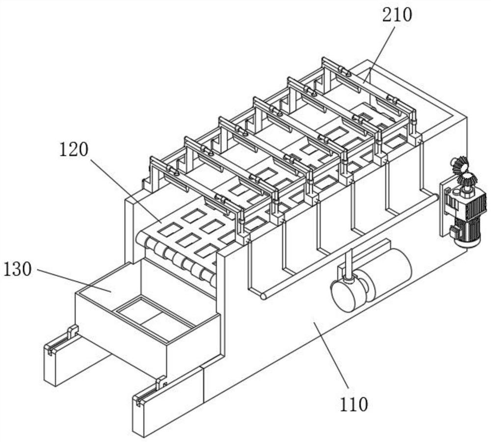
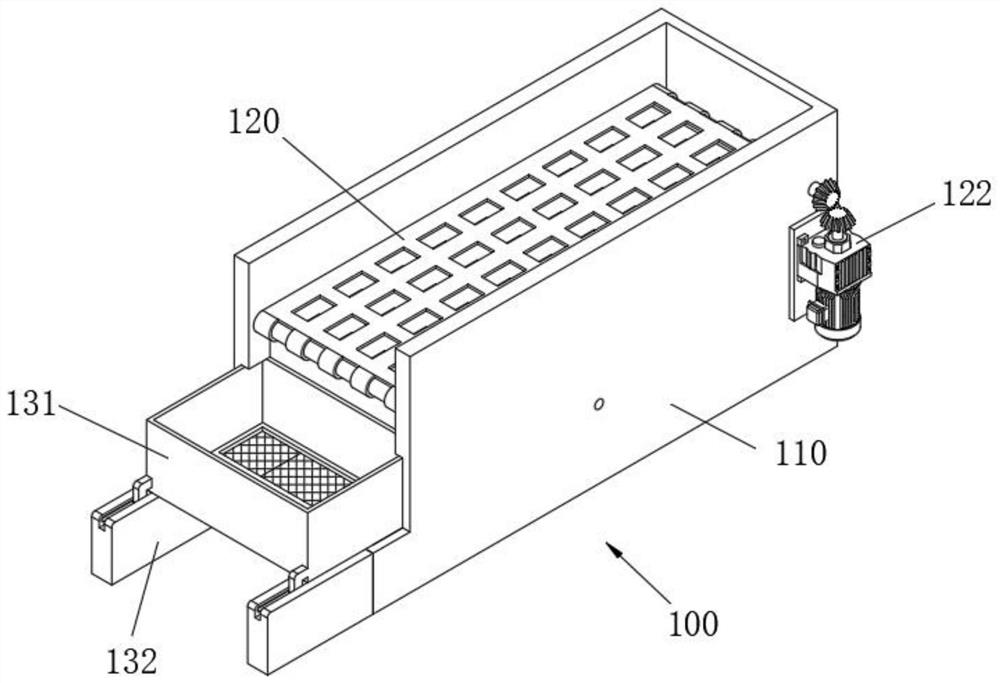
[0047] see Figure 1-Figure 9 As shown, the purpose of this embodiment is to provide a transmission type hay cleaning equipment with a scouring structure, including a transmission structure 100 and a cleaning structure 200 installed above the transmission structure 100;
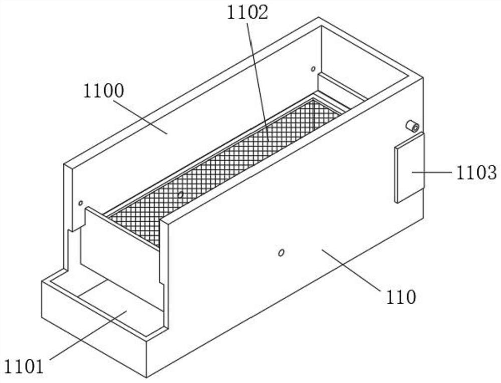
[0048]The transmission structure 100 at least includes a cleaning box 110, the inside of the cleaning box 110 is provided with a cleaning power 1100, and the inside of the cleaning power 1100 is provided with a conveyor belt 120 for conveying hay, and the inner two ends of the conveyor belt 120 are connected with a rolling rod 121, and the rolling rod 121 It is rotatably connected with the front and rear ends of the cleaning box 110, and is used to drive the transmission of the conveyor belt 120, thereby driving the hay on its surface to move. The interior of the conveyor belt 120 is provided with an empty groove 1200, and a water storage tank 1101 is provided below the cleaning power 1100 for recycling cleani...
Embodiment 2
[0064] For collection and discharge of washed hay, see image 3 and Figure 5 As shown, the purpose of this embodiment is: the transmission structure 100 also includes a collection device 130, the collection device 130 at least includes a collection box 131, the collection box 131 is located below the rear end of the conveyor belt 120, and the inside of the collection box 131 is provided with a collection chamber 1310 for collecting Cleaned hay is collected;
[0065] In order to filter out the moisture on the dry grass surface, a collection chamber filter screen 1311 is installed at the front opening of the bottom surface of the collection chamber 1310, and the collection chamber filter screen 1311 is located above the rear opening of the water storage tank 1101. The cleaning water remaining on the surface is filtered to the inside of the water storage tank 1101 to be collected;
[0066] In order to discharge the hay inside the collection chamber 1310, the rear end both side...
PUM
 Abstract
Description
Claims
Application Information
 - R&D
- Intellectual Property
- Life Sciences
- Materials
- Tech Scout
- Unparalleled Data Quality
- Higher Quality Content
- 60% Fewer Hallucinations
Browse by: Latest US Patents, China's latest patents, Technical Efficacy Thesaurus, Application Domain, Technology Topic, Popular Technical Reports.
© 2025 PatSnap. All rights reserved.Legal|Privacy policy|Modern Slavery Act Transparency Statement|Sitemap|About US| Contact US: help@patsnap.com


