Toilet flusher with novel valves and controls

a technology of valves and controls, applied in the field of toilet flushing, can solve problems such as reducing the effectiveness of the flush valve seal

Inactive Publication Date: 2004-02-12
ARICHELL TECH INC
View PDF64 Cites 45 Cited by
  • Summary
  • Abstract
  • Description
  • Claims
  • Application Information

AI Technical Summary

Problems solved by technology

Also, high line pressure actually aids in preventing leakage through the flush

Method used


Image

  • Toilet flusher with novel valves and controls
  • Toilet flusher with novel valves and controls
  • Toilet flusher with novel valves and controls

Examples


Embodiment Construction

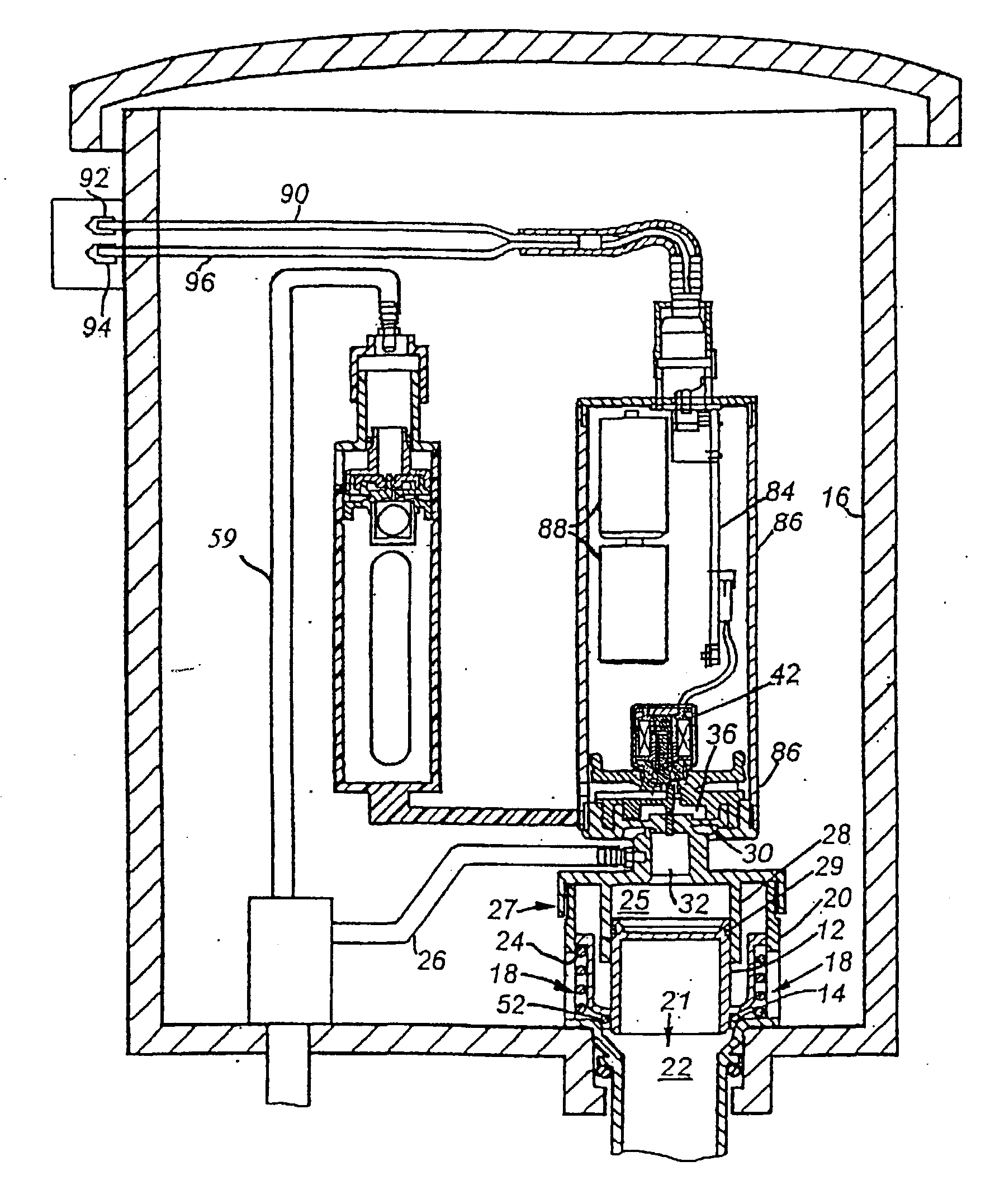
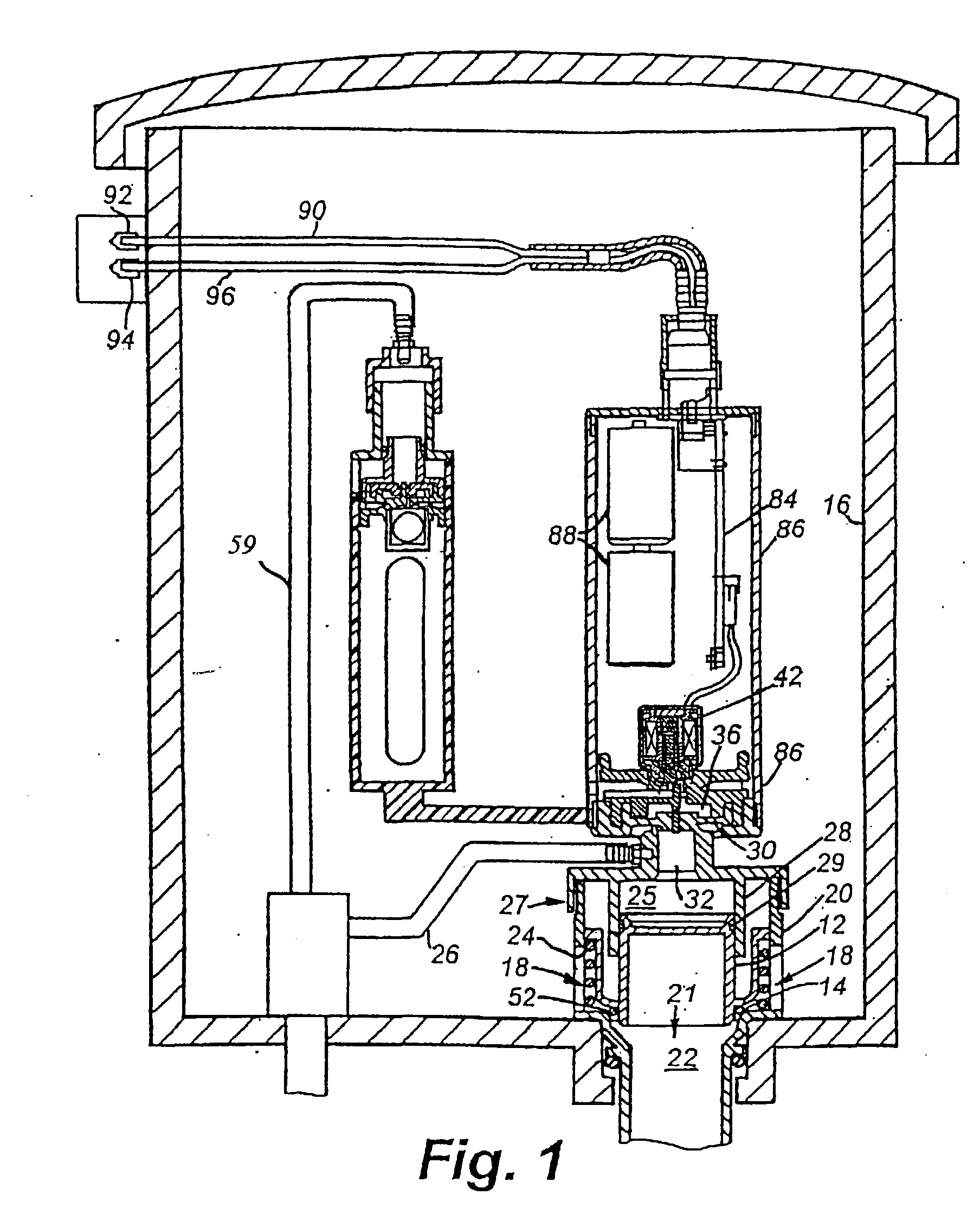
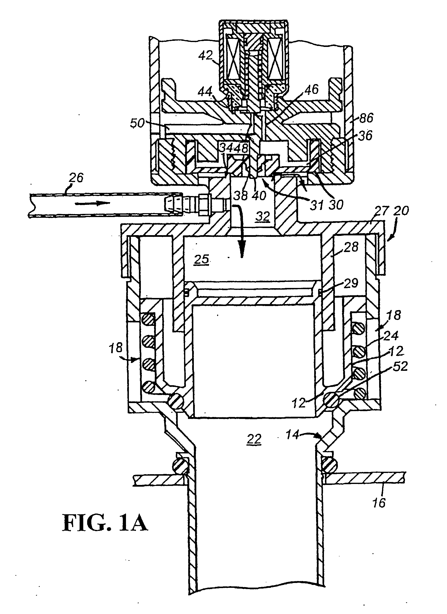
[0048] Referring to FIG. 1, a gravity-type flush mechanism includes a fill valve mechanism 5 and a flush-valve mechanism 10 located in a toilet tank 16. Toilet tank 16 is an exposed tank traditionally used in the US, or a concealed tank frequently used in the EU countries. FIG. 1A shows flush-valve mechanism 10 in a closed state wherein flush-valve member 12 is seated in a flush-valve seat 14 formed in the bottom of toilet tank 16. In that seated position, the valve member 12 prevents water from the tank 16 that has entered through flush ports 18 in a flush-valve housing 20 from flowing through a flush outlet 21 and a flush conduit 22 to a toilet.

[0049] The flush mechanism includes a bias spring 24, which exerts a force that tends to urge flush-valve member 12 off its seat 14. That is, flush-valve member 12 is biased to an unsealed state but remains seated between flushes due to water line pressure. This pressure that normally prevails in a flush-valve (or piston) chamber 25 because...


PUM


Abstract

A tank-type flusher includes an intake valve, i.e., a fill valve, a diaphragm-operated flush valve, and a pressure control mechanism. The intake valve is connected to an external water source and is constructed to close water flow to a water storage tank at about a predefined water level in the water tank. The diaphragm-operated flush valve is constructed to control a flush valve member between a seated state and an unseated state allowing water discharge from the water tank into a toilet bowl. There is a diaphragm, separating a flush-valve chamber and a pilot chamber, arranged to seal the flush-valve chamber and thereby maintain pressure forcing the flush valve member to the seated state preventing the water discharge from the water storage tank to the toilet bowl. The pressure control mechanism is constructed and arranged, upon actuation, to reduce pressure in the pilot chamber of the diaphragm-operated flush valve to cause deformation of the diaphragm and thereby reduce pressure in the flush-valve chamber causing the water discharge.

Description

[0001] This application claims priority from PCT Application PCT / US01 / 43273, filed Nov. 20, 2001, which is a continuation-in-part of U.S. application Ser. No. 09 / 716,870, entitled "Timed Fluid-Linked Flush Controller," filed on Nov. 20, 2000; U.S. application Ser. No. 09 / 761,408, entitled "Flusher Having Consistent Flush-Valve-Closure Pressure," filed on Jan. 16, 2001; U.S. application Ser. No. 09 / 761,533, entitled "Supply-Line-Sealed Flush Controller," filed on Jan. 16, 2001; PCT Application PCT / US01 / 11384, entitled "Automatic Tank-Type Flusher," filed on Apr. 6, 2001; and U.S. application Ser. No. 09 / 957,761 entitled "Push Button For Metered Flow," filed on Sep. 21, 2001.[0002] 1. Field of the Invention[0003] The present invention is directed to toilet flushing. It finds particular, although not exclusive, application in automatic tank-type flushers.[0004] 2. Background Information[0005] The art of toilet flushers is an old and mature one. (We use the term toilet here in its broad...

Claims


Application Information

Patent Timeline
IPC IPC(8): E03D1/14E03D3/06E03D5/02
CPCE03D1/142E03D1/30F16K31/406E03D5/024E03D5/10E03D3/06
Inventor PARSONS, NATAN E.GULER, FATIHHERBERT, KAYHADLEY, DAVIDSHAMITZ, ROBERT
Owner ARICHELL TECH INC
Why Eureka
Try Eureka