
Hydrogen-oxygen/hydrocarbon fuel system for internal combustion engine

a fuel system and hydrogen-oxygen technology, applied in the field of fuel/gas delivery system, can solve the problems of occupying valuable space and adding weight to the vehicl

Inactive Publication Date: 2001-11-06
LAROCQUE JEAN LOUIS
View PDF8 Cites 81 Cited by
  • Summary
  • Abstract
  • Description
  • Claims
  • Application Information

AI Technical Summary

Benefits of technology

An important object of the invention is to improve upon the fuel / gas delivery system described in U.S. Pat. No. 5,546,902, supra, by completely eliminating the toxic CO by-products from automobile internal combustion engines.
A general object of the invention is to enhance the combustion process and increase the efficiency of internal combustion engines by reducing the level of exhaust emissions from the automobile internal combustion engine.
An object of the invention is to decrease fuel consumption of automobiles with internal combustion engines.
A further object of the invention is to increase the travelling range of the automobile for a given volume of fuel.
Preferably, a water filter is mounted to said second fluid line for preventing accidental liquid water seeping from said inner housing into the fuel tank.
An electrically insulating sheath member may be fitted to an intermediate section of said second fluid line for preventing accidental transmission of electric current from said electrolytic chamber to the fuel tank.

Problems solved by technology

However, such device requires a substantial "on-board" hydrogen generating capacity, to meet the large consumption of hydrogen, which consumes energy, occupies valuable space and adds weight to the vehicle.

Method used


Image

  • Hydrogen-oxygen/hydrocarbon fuel system for internal combustion engine
  • Hydrogen-oxygen/hydrocarbon fuel system for internal combustion engine
  • Hydrogen-oxygen/hydrocarbon fuel system for internal combustion engine

Examples


Embodiment Construction

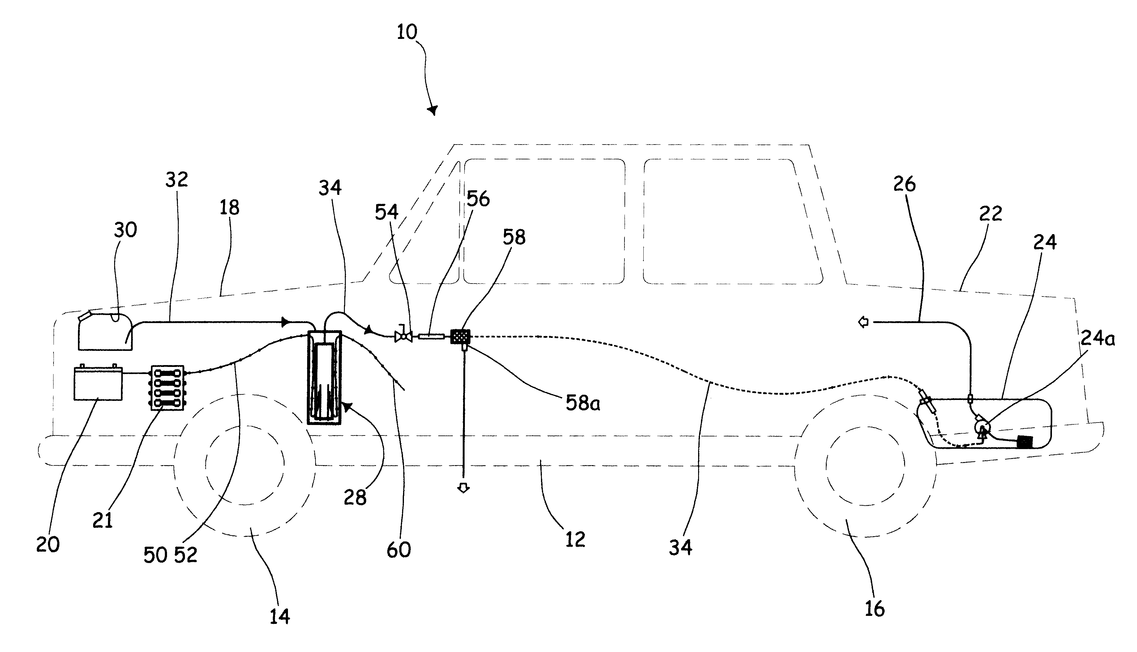
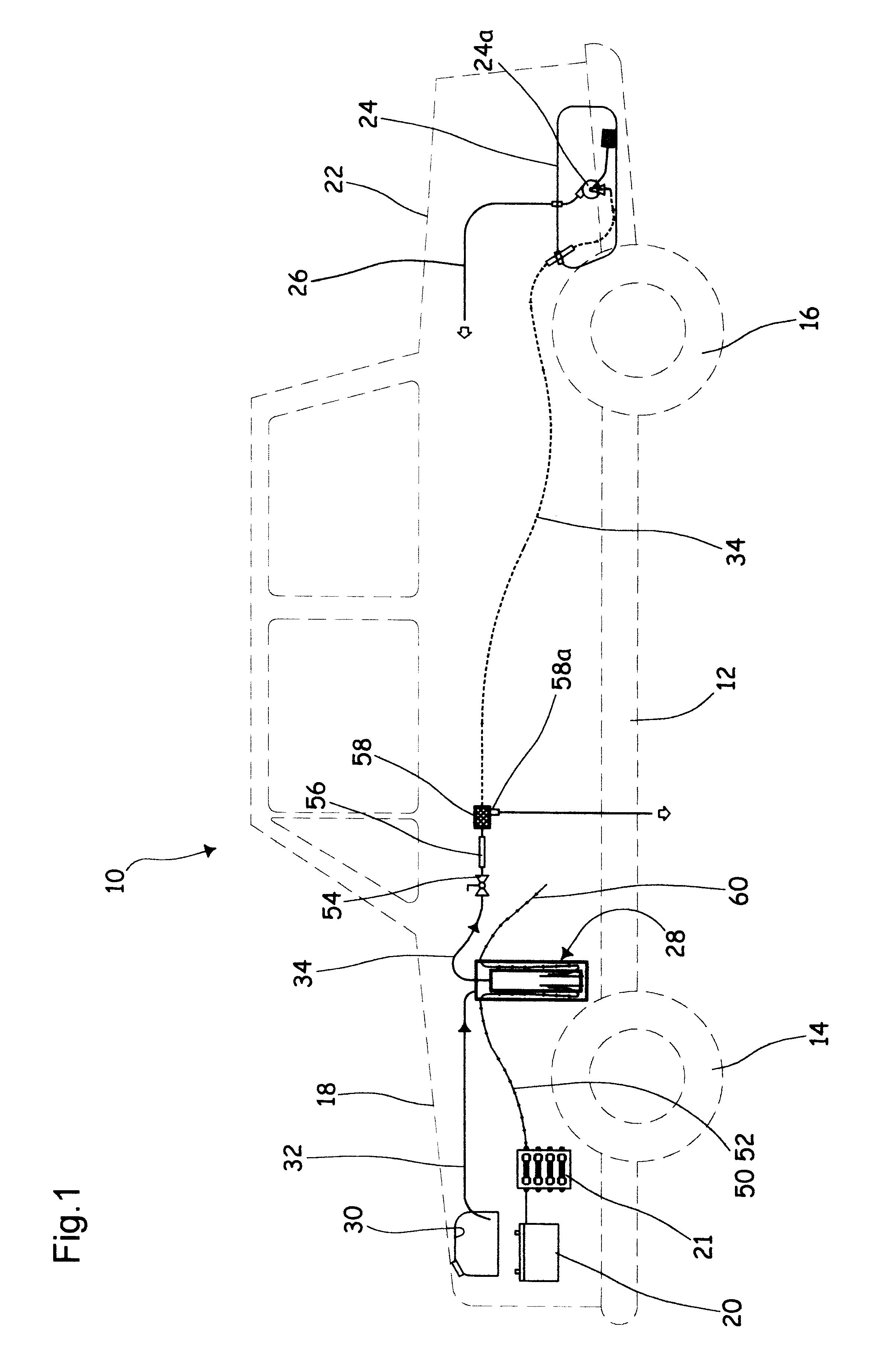
The automobile illustrated in FIG. 1 as 10 conventionally includes a chassis 12 carried over ground by a first pair of front axle wheels 14 and by a second pair of rear axle wheels 16. Under the front hood 18 is found the motor engine, not shown, and under the rear trunk 22 is found the fuel tank 24. The fuel tank 24 is fluidingly connected to the motor engine (not illustrated) via a flexible fuel line 26.

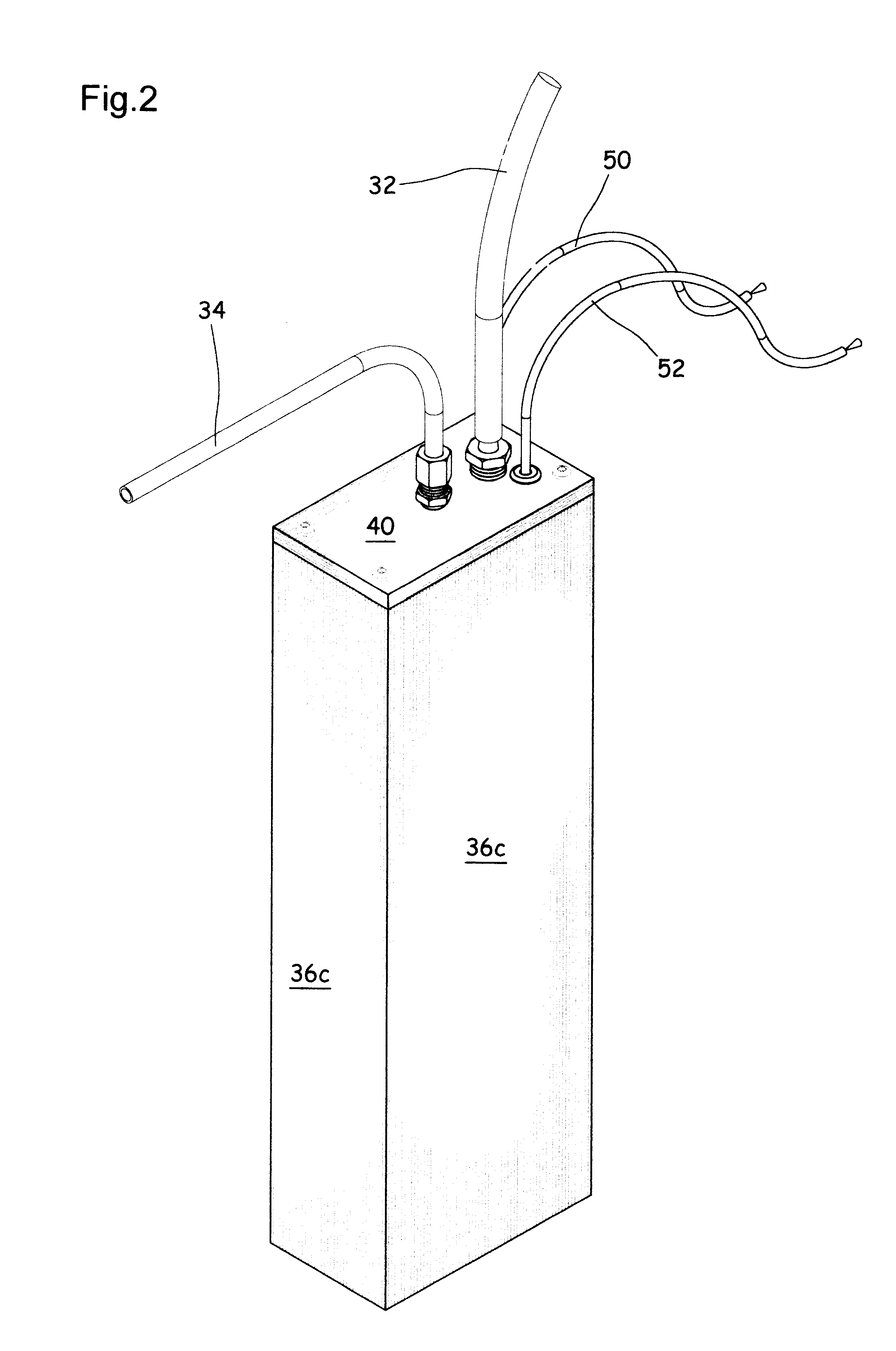
Accordingly with the invention, there is provided under the hood 18 an on-board electrolytic chamber 28, anchored to the automobile chassis. A high-salt content water tank 30 is further provided under the hood, preferably anchored to and adjacent of the conventional windshield wiper fluid tank (not illustrated). Salt concentration in the water is preferably of about 160 grams per liter of water. The volumic content of water tank 30 is for example half a liter. The added salt is to increase conductivity of the solution and to prevent ice formation in sub-freezing conditions. A first...


PUM

PropertyMeasurementUnit
concentrationaaaaaaaaaa
diameteraaaaaaaaaa
sizeaaaaaaaaaa

Abstract

A device for injection of molecular hydrogen and oxygen into the combustion chambers of a gasoline engine, along with the fuel-air mixture, to improve fuel efficiency and to reduce and in some cases eliminate engine emissions. The hydrogen-oxygen / hydrocarbon fuel system includes: a water source; an electrolytic chamber, an anode and a cathode mounted into the chamber in closely spaced fashion from one another; two fluid lines to fluidingly connect the water source and the fuel tank to the chamber; and an electrical power source, for electrically charging the anode and cathode.

Description

This invention relates to device for enhancing fuel combustion in an internal combustion engine, while improving the engine efficiency and eliminating at least one toxic by-product from its combustion.Major industrial countries in the world now have regulations relating to the level of exhaust emissions from automobiles, which are imposing progressively reduced permitted levels of internal combustion engine emissions. This in turn increases the demand for greater control of the combustion process of the internal combustion engines.U.S. Pat. No. 3,906,913 issued in September 1975 to the CALIFORNIA INSTITUTE OF TECHNOLOGY, discloses a device for mixing hydrogen with hydrocarbon fuel and air for use in the internal combustion engine of an automobile. However, such device requires a substantial "on-board" hydrogen generating capacity, to meet the large consumption of hydrogen, which consumes energy, occupies valuable space and adds weight to the vehicle.U.S. Pat. No. 5,546,902 issued on...

Claims


Application Information

Patent Timeline
Patent Type & Authority Patents(United States)
IPC IPC(8): F02D19/08F02D19/00F02M25/12F02B43/00F02B43/10F02M25/00
CPCF02B43/10F02M25/12F02D19/0644F02D19/0665F02D19/0671F02D19/081Y02T10/121F02D19/0697Y02T10/36Y02T10/32Y02T10/12Y02T10/30
Inventor LAROCQUE, JEAN-LOUIS
Owner LAROCQUE JEAN LOUIS
Learn More