Community national fitness equipment power generation equipment

A technology of fitness equipment and power generation equipment, which is applied in the field of community fitness equipment power generation equipment, can solve problems such as high exercise intensity, and achieve the effect of energy saving and rapid power generation

Pending Publication Date: 2022-01-25
江苏杰优新能源科技有限公司
View PDF0 Cites 0 Cited by
  • Summary
  • Abstract
  • Description
  • Claims
  • Application Information

AI Technical Summary

Problems solved by technology

[0003] The purpose of the present invention is to provide community fitness equipment power generation equipment to solve the problem in the above-mentioned background technology that the exercise intensity required for power generation equipment is too large

Method used


Image

  • Community national fitness equipment power generation equipment
  • Community national fitness equipment power generation equipment
  • Community national fitness equipment power generation equipment

Examples


Embodiment 1

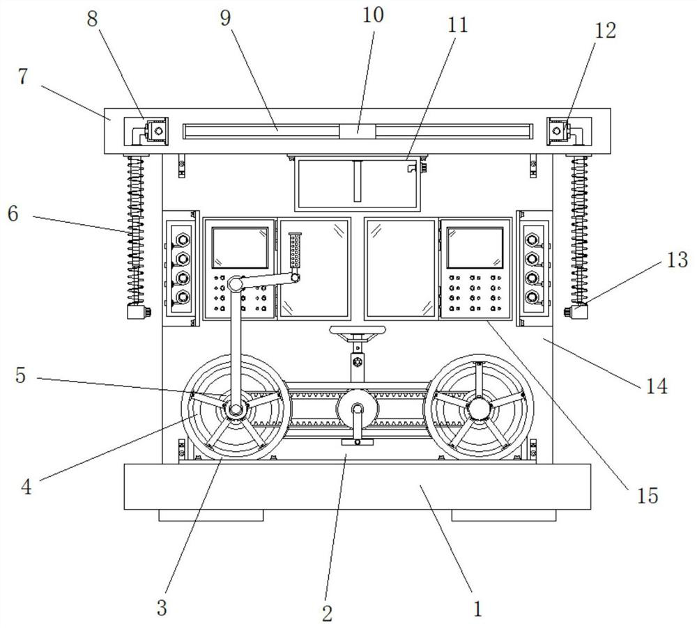
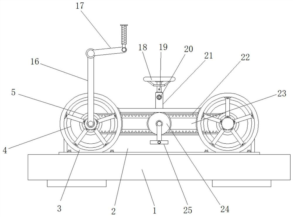
[0025] Example 1: See Figure 1-5 , community fitness equipment power generation equipment, including a base 1 and a fixed cavity 2, the front end of the top of the base 1 is welded with a fixed cavity 2, the two sides of the fixed cavity 2 are respectively provided with a circular frame 3, a circular frame 3 A positioning frame body 23 is installed between one side of the base 1, and a wall panel 14 is fixedly installed between the two sides of the top rear end of the base 1. The top of the wall panel 14 is fixedly welded with a cover plate 7, and the two sides of the front end of the wall panel 14 are respectively An operation panel 15 is installed, grooves 34 are respectively arranged inside the two sides of the wallboard 14, and a housing 35 is installed inside the groove 34;

[0026] The inside of the circular frame 3 is movably connected with a tire 4, the diameter of the tire 4 is smaller than the inner diameter of the circular frame 3, and the rods at both ends of the ...

Embodiment 2

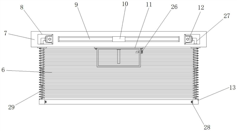
[0028] Embodiment 2: The center of the bottom of the cover plate 7 is fixedly connected with a liquid storage box 11, the top of the right side of the liquid storage box 11 is provided with a water injection nozzle 26, and the insides of both sides of the cover plate 7 are respectively provided with Reservation groove 8, the inside of reservation groove 8 is provided with miniature water pump 12, and the center of cover plate 7 inside is covered with three-way water pipe 10, and the two sides of three-way water pipe 10 are respectively fixed with communicating conduit 9, and connecting conduit 9 and The input end of miniature water pump 12 is connected, and the bottom of three-way water pipe 10 probes in the liquid storage box 11, and the both sides of cover plate 7 bottom ends are respectively equipped with electric telescopic rod 29, and the bottom of electric telescopic rod 29 is connected There is a semi-arc-shaped plate 13, and a plurality of groups of atomizing nozzles 28...

Embodiment 3

[0030] Embodiment 3: One side of the operation panel 15 is movably hinged with a transparent flap 30, the top of the front end of the operation panel 15 is provided with a display screen 32, and the bottom of the front end of the operation panel 15 is provided with multiple groups of power-on buttons 31, and one side of the power-on button 31 An indicator light 33 is provided, and the inside of the housing 35 is movably connected with multiple groups of winding reels 36, and a connecting sleeve 37 is arranged on the rod body at the center of the rewinding reels 36, and the rewinding reels 36 are arranged at equal intervals inside the housing 35. The connecting sleeve 37 is embedded in the through groove on one side of the housing 35, and the two sides of the wall panel 14 are respectively equipped with a generator 40, and a transmission shaft 38 is connected between the generator 40 and the tire 4, and the center of the wall panel 14 is A shunt 39 is provided, and there is an e...


PUM


Abstract

The invention discloses community national fitness equipment power generation equipment which comprises a base and a fixed cavity. The fixed cavity is welded to the front end of the top of the base, circular frames are arranged on the two sides of the fixed cavity correspondingly, a positioning frame is installed between one sides of the circular frames, a wall plate is fixedly installed between the two sides of the rear end of the top of the base, and a shielding cover plate is fixedly welded to the top of the wall plate. According to the community national fitness equipment power generation equipment, the fixed cavity is welded to the front end of the top of the base, a user adjusts the height of an inserting connection rod in a hollow sleeve rod, then locks a fixed bolt, sits on a sponge cushion and holds a handrail to circularly tread pedals, a driving fluted disc drives a side fluted disc to rotate through a metal chain belt so that a power generator in the wall plate can work. Bicycle type sports equipment is provided with the sponge cushion for exercisers to sit for sports, so that compared with running, swimming and other projects, a lot of physical strength can be saved, and the problem that the exercise intensity needed by power generation equipment is large is solved.

Description

technical field [0001] The invention relates to the technical field of fitness power generation equipment, in particular to community fitness equipment power generation equipment for all people. Background technique [0002] In order to improve their overall physical fitness, more and more people choose morning exercises and fitness, which not only burn excess fat, but also relieve stress and exercise the heart and muscles. Among these sports, running, cycling, and aerobic exercise have become It is the first choice of people, and on this basis, the designer has developed a power generation device that can convert the kinetic energy generated into electric energy for use by the community or other people while exercising. In today's pursuit of saving electricity, this device The invention of the device has undoubtedly contributed to a win-win situation for both fitness and power generation, but such devices in the past have more or less problems such as heavy use and cumberso...

Claims


Application Information

Patent Timeline
Patent Type & Authority Applications(China)
IPC IPC(8): F03G5/02A63B22/08A61L2/22A61L2/26
CPCF03G5/02A63B22/0605A61L2/22A61L2/26
Inventor 李杰吴慧娟
Owner 江苏杰优新能源科技有限公司
Why Eureka
Try Eureka