
Recoverable anchorage device

A technology of anchorage and body, applied in the field of anchorage, can solve the problems such as inconvenient recovery of steel strands, and achieve the effect of simple and convenient operation

Pending Publication Date: 2022-01-28
HENGYANG CITY XINDELI PRESTRESSED CO LTD
View PDF11 Cites 0 Cited by
  • Summary
  • Abstract
  • Description
  • Claims
  • Application Information

AI Technical Summary

Problems solved by technology

[0002] Anchor refers to the permanent anchoring device used in prestressed concrete. It is an anchoring tool used in post-tensioned structures or components to maintain the tension of the prestressed tendon and transfer it to the interior of the concrete. It is also called a prestressed anchor. The clip-type anchor is to use the wedge-tight principle of the tapered hole to anchor the steel strand, that is, the wedge-shaped clip anchors the steel strand in the tapered hole of the anchor plate. When the jack is used to tension the steel strand, it can reach After the design stress value, the jack is slowly released, and the clip of the anchorage is brought into the tapered hole of the anchor plate by the steel strand that retracts at a uniform speed, forming an anchoring unit. The stress of the steel strand passes through the anchor plate and the anchor plate. The backing plate is transferred to the building structure to form a permanent prestress. The anchorage needs to recover the steel strand when it is used, but the existing anchorage cannot conveniently recover the steel strand

Method used


Image

  • Recoverable anchorage device
  • Recoverable anchorage device
  • Recoverable anchorage device

Examples


Embodiment 1

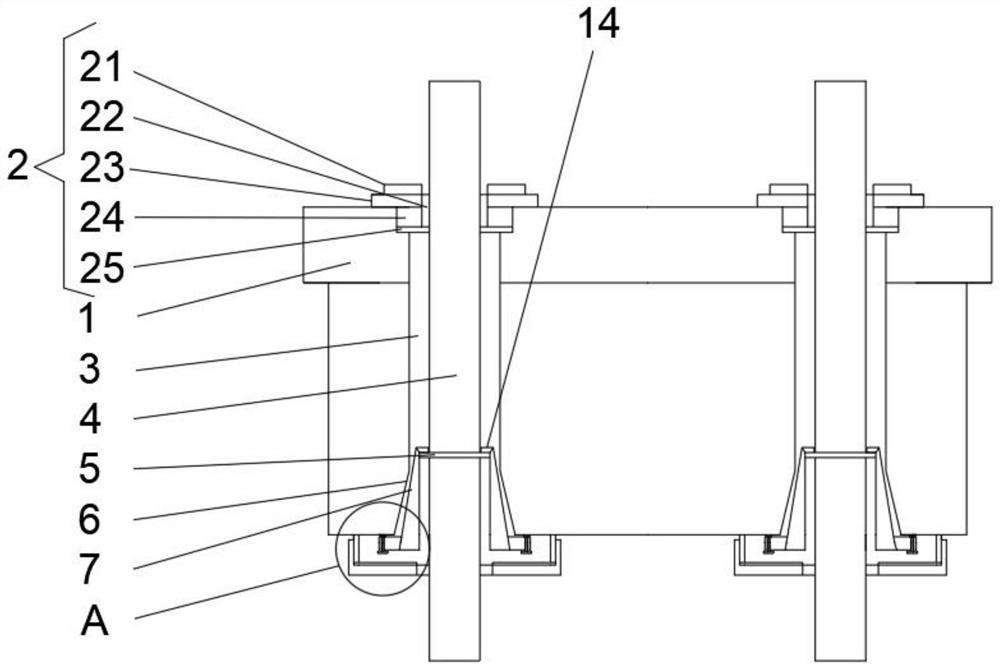
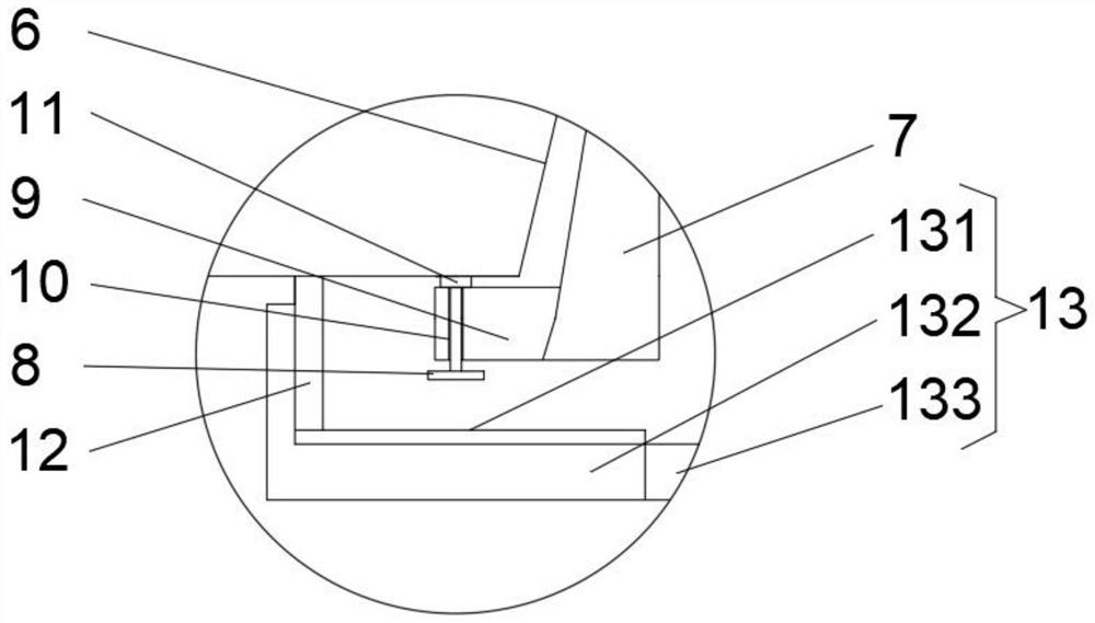
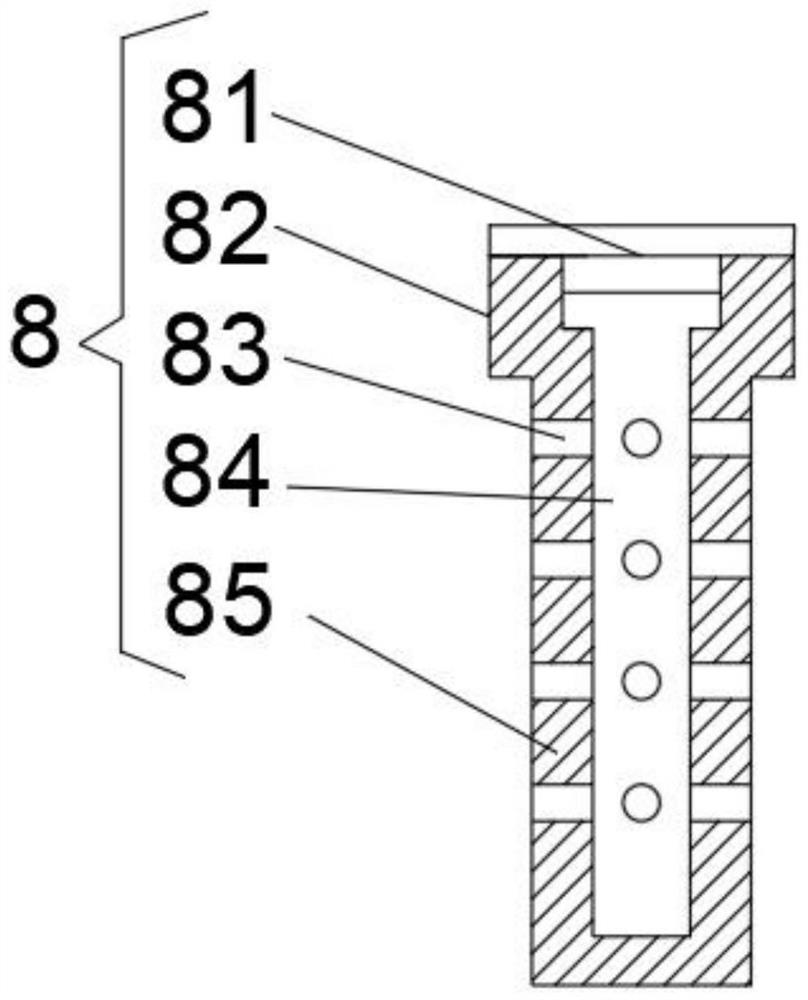
[0026] Such as Figure 1-3 As shown, a recyclable anchor described in this embodiment includes an anchor body 1, and the upper end of the anchor body 1 is uniformly provided with a vertical hole 3 passing through the upper and lower ends, and the vertical hole 3 is inserted with a steel strand 4 from the lower end. , the upper end of the vertical hole 3 is screwed with the upper sealing structure 2, the lower end of the vertical hole 3 is provided with a tapered hole 6, and the tapered hole 6 is inserted with a tapered cylinder 7, and the tapered cylinder 7 is composed of two semi-conical cylinders , the upper end of the conical cylinder 7 is provided with an annular stopper 17, the steel strand 4 is provided with a snap ring 5 at the lower end of the annular stopper, and the lower end of the conical cylinder 7 protrudes from the bottom side of the tapered hole 6;

[0027] The outside of the lower end of the tapered cylinder 7 is equipped with an annular baffle 9, and the two ...


PUM


Abstract

The invention discloses a recoverable anchorage device which comprises an anchorage device body, vertical holes penetrating up and down are evenly formed in the upper end of the anchorage device body, steel strands are inserted from the lower ends of the vertical holes, upper sealing structures are in threaded connection with the upper ends of the vertical holes, conical holes are formed in the lower ends of the vertical holes, conical barrels are inserted into the conical holes, and each conical barrel is composed of two semi-conical cylinders, an annular stop block is arranged at the upper end of the conical barrel, a clamping ring is arranged at the position, at the lower end of the annular stop block, of the steel strand, and the lower end of the conical barrel extends out of the bottom side of the conical hole, an annular baffle is assembled on the outer side of the lower end of the conical barrel, threaded holes are formed in the two ends of the lower side of the annular baffle, the threaded holes penetrate through the annular baffle, and anti-rust bolts are screwed into the threaded holes, the length of a stud of the anti-rust bolt is larger than the thickness of the annular baffle, and the anchorage device body is provided with an ejector block at the upper end of the anti-rust bolt. According to the scheme, the anti-rust bolt can eject out of the conical barrel, so that the two semi-conical cylinders of the conical barrel are separated, the steel strand rope is not clamped any more, and then the steel strand rope is recycled.

Description

technical field [0001] The invention belongs to the technical field of anchors, and in particular relates to a recoverable anchor. Background technique [0002] Anchor refers to the permanent anchoring device used in prestressed concrete. It is an anchoring tool used in post-tensioned structures or components to maintain the tension of the prestressed tendon and transfer it to the interior of the concrete. It is also called a prestressed anchor. The clip-type anchor is to use the wedge-tight principle of the tapered hole to anchor the steel strand, that is, the wedge-shaped clip anchors the steel strand in the tapered hole of the anchor plate. When the jack is used to tension the steel strand, it can reach After the design stress value, the jack is slowly released, and the clip of the anchorage is brought into the tapered hole of the anchor plate by the steel strand that retracts at a uniform speed, forming an anchoring unit. The stress of the steel strand passes through the...

Claims


Application Information

Patent Timeline
Patent Type & Authority Applications(China)
IPC IPC(8): E04C5/12E04C5/08
CPCE04C5/12E04C5/122
Inventor 谭庆华罗泽顺罗芝平
Owner HENGYANG CITY XINDELI PRESTRESSED CO LTD
Learn More