Backlight driving power protection method and system, display device and storage medium
A technology for backlight drive and display equipment, applied to static indicators, instruments, etc., can solve problems such as damage to power devices, frequent actions of protection circuits, etc.
- Summary
- Abstract
- Description
- Claims
- Application Information
AI Technical Summary
Problems solved by technology
Method used
Image
Examples
Embodiment 1
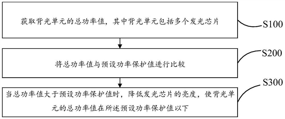
[0046] Such as figure 1 As shown, this embodiment proposes a power protection method for backlight driving, which is applied to the backlight unit of a display device. This power protection method mainly includes steps:
[0047] Step S100, acquiring the total power value of the backlight unit.
[0048] In a specific process, the backlight unit includes a plurality of light-emitting chips; the total power value of the backlight unit is the sum of the power values of the plurality of light-emitting chips.
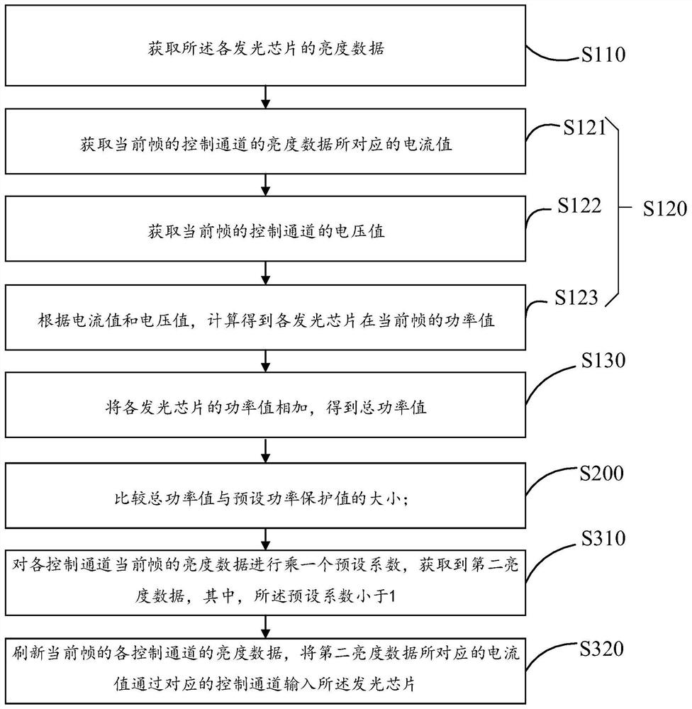
[0049] Such as figure 2 As shown, the step S100 specifically includes:
[0050] Step S110, acquiring brightness data of each light-emitting chip.
[0051] In a specific process, the light-emitting chip is driven by the backlight driver chip to emit light, and the backlight driver chip receives the luminance data and drives the corresponding light-emitting chip to emit light. The luminance data is a parameter for controlling the luminous brightness of the light-emitting...
Embodiment 2
[0072] Such as image 3 As shown, on the basis of Embodiment 1 and based on the same inventive concept, the present invention also proposes a backlight driving power protection system, which includes: a power acquisition module 10 , a power comparison module 11 , and a power reduction module 12 . The power acquisition module 10 is used to acquire the total power value of the backlight unit 40 , wherein the backlight unit 40 includes a plurality of light emitting chips 41 . The comparing power module 11 is used for comparing the total power value with a preset power protection value. The power reduction module 12 is used for reducing the brightness of the light-emitting chip 41 when the total power value is greater than the preset power protection value, so that the total power value of the backlight unit is below the preset power protection value.
[0073] Through the above scheme, a power protection value is preset, and the power protection value is smaller than the protecti...
Embodiment 3
[0075] Such as Figure 4 As shown, on the basis of Embodiment 1, based on the same inventive concept, the present invention also proposes a display device, which includes: a processor 20 (MCU), a backlight driver chip 31 (Mini LED Driver IC), and a backlight unit 40 (Mini LED Light Bar Unit), the backlight unit 40 includes a plurality of light emitting chips 41 (Mini LED). The processor 20 and the backlight driver chip 31 form a backlight driver unit 30 (Mini LED Driver Unit), the processor 20 is connected to the backlight driver chip 31, and is used to obtain the total power value of the backlight unit 40 and compare the total The size of the power value and the preset power protection value. The backlight driver chip 31 is connected to the backlight unit 40, and is used for reducing the brightness of the light-emitting chip 41 when the total power value is greater than a preset power protection value, wherein the brightness of the light-emitting chip 41 is positive to the t...
PUM
 Abstract
Description
Claims
Application Information
 - R&D
- Intellectual Property
- Life Sciences
- Materials
- Tech Scout
- Unparalleled Data Quality
- Higher Quality Content
- 60% Fewer Hallucinations
Browse by: Latest US Patents, China's latest patents, Technical Efficacy Thesaurus, Application Domain, Technology Topic, Popular Technical Reports.
© 2025 PatSnap. All rights reserved.Legal|Privacy policy|Modern Slavery Act Transparency Statement|Sitemap|About US| Contact US: help@patsnap.com


