Video monitoring device of computer network

A computer network and video surveillance technology, which is applied to TVs, color TVs, components of color TVs, etc., can solve the problems of poor stability of shock absorption, lens shaking, and can not effectively solve the following problems of the lens, so as to reduce the lens shaking. The effect of frequency

Pending Publication Date: 2022-01-28
广西柳钢东信科技有限公司 +1
View PDF0 Cites 1 Cited by
  • Summary
  • Abstract
  • Description
  • Claims
  • Application Information

AI Technical Summary

Problems solved by technology

[0003] However, in actual use, it is often restricted by the installation position of the video surveillance device, causing the camera to shake during use, which affects the user experience, and the shock absorption method of the general body is mostly through built-in gaskets, springs, etc. structure, to avoid the follow-up movement of the shock-absorbing shell and the lens body of the video surveillance device, but this type of shock-absorbing method is less stable, and the shock-absorbing buffer space of the device is limited, so it cannot effectively solve the problem of the lens following the shaking, and The body and the shock absorbing part are mostly fixed with screws, which increases the difficulty of maintenance and replacement of the device. For this reason, we propose a computer network video monitoring device

Method used


Image

  • Video monitoring device of computer network
  • Video monitoring device of computer network
  • Video monitoring device of computer network

Examples


Embodiment 1

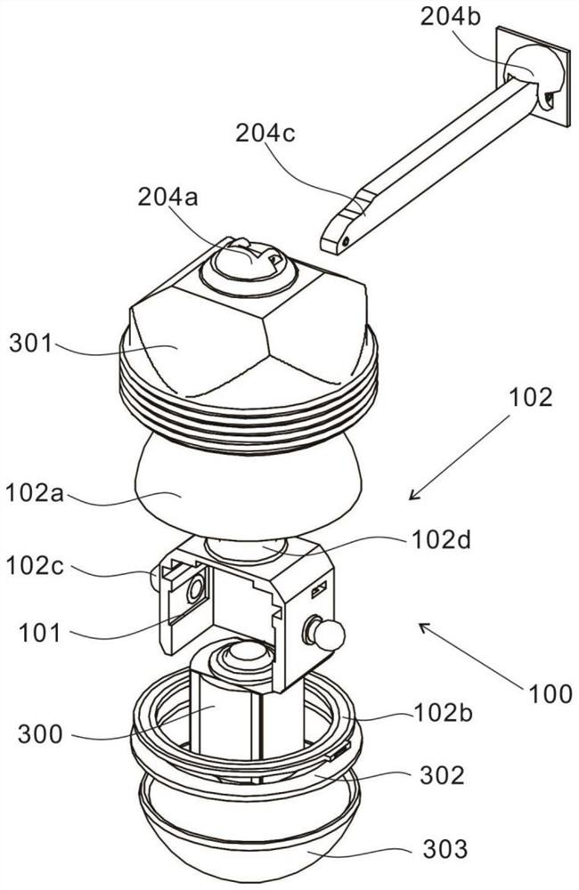
[0028] refer to figure 1 A computer network video monitoring device includes a shock absorbing device 100 , a fixing device 200 and a monitoring device 300 .

[0029] Specifically, the shock absorbing device 100 is used to stabilize the monitoring device 300, which includes a shock absorbing housing 101 and an electromagnetic assembly 102, and the electromagnetic assembly 102 is placed outside the shock absorbing housing 101 to make the monitoring device 300 tend to be suspended and stable.

[0030] Specifically, the fixing device 200 is used to connect the shock absorbing device 100 and the monitoring device 300 .

[0031] Specifically, the monitoring device 300 includes a monitoring device housing 301 , the monitoring device 300 is fixed on the shock absorbing housing 101 through the fixing device 200 , and the shock absorbing housing 101 is movably installed inside the monitoring device housing 301 through the electromagnetic assembly 102 .

[0032] Further, the electromag...

Embodiment 2

[0038] refer to figure 1 with figure 2 , this example is based on the first example is:

[0039] The electromagnetic top cover 102a is electrically connected to the track magnetic ring 102b, and the electromagnetic lifting ball 102c is electrically connected to the electromagnetic mutual repulsion ball 102d, so that two of them can generate force simultaneously.

[0040] Wherein, the opposite surface of the electromagnetic top cover 102a and the track magnetic ring 102b shows the same polarity magnetic pole, and the electromagnetic lifting ball 102c shows the magnetic field of the same level as the top of the electromagnetic mutual repulsion ball 102d outside the bottom of one end of the shock absorbing housing 101, and the electromagnetic top cover The opposite surface of 102a and the track magnetic ring 102b, the bottom of the electromagnetic lifting ball 102c away from the end of the shock absorbing shell 101, and the top of the electromagnetic mutual repulsion ball 102d ...

Embodiment 3

[0044] refer to Figure 2 ~ Figure 4 , this embodiment is different from the above embodiments in that: the fixing methods of the monitoring device 300 and the shock-absorbing housing 101 are different.

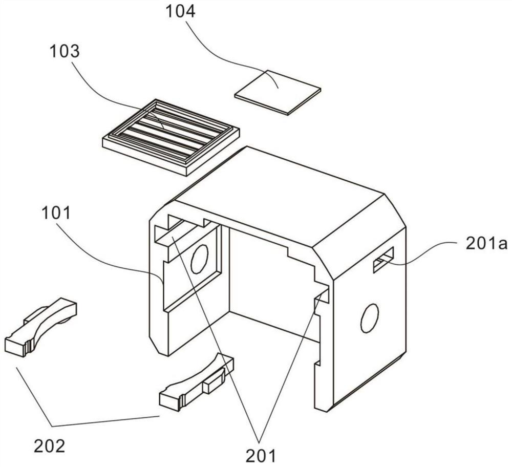
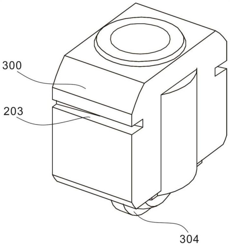
[0045] Specifically, the fixing device 200 is used to fix the shock-absorbing housing 101 and the monitoring device 300, and includes a latch slide 201, a mounting pin 202 and a mounting card slot 203, and the latch slide 201 is symmetrically arranged on the shock-absorbing housing 101. , the installation card slot 203 is arranged on the monitoring device 300, and the installation pin 202 is detachably placed on the latch slide slot 201 and in the installation card slot 203 to connect and disassemble the shock absorbing shell 101 and the monitoring device 300.

[0046] Further, a fixed fastener 202a is slidably connected to the installation bolt 202, and one end of the fixed fastener 202a close to the installation bolt 202 is fixedly connected with a pushing spring 202b, and ...


PUM


Abstract

The invention discloses a video monitoring device for a computer network, and the device comprises a damping device which comprises a damping shell and an electromagnetic assembly, and the electromagnetic assembly being disposed at the outer side of the damping shell; a fixing device; and a monitoring device, comprising a monitoring device shell, the monitoring device being fixed to the damping shell through the fixing device, and the damping shell being movably installed in the monitoring device shell through the electromagnetic assembly. The electromagnetic assembly comprises an electromagnetic top cover arranged at the top of the inner side of the monitoring device shell, a track magnetic ring arranged at the bottom of the inner side of the monitoring device shell, electromagnetic lifting balls arranged on the two sides of the damping shell, the electromagnetic lifting balls and the track magnetic ring being used in cooperation, an electromagnetic mutual exclusion ball arranged at the center of the top of the damping shell being used in cooperation with the electromagnetic top cover. The device has a damping effect on the monitoring device, and the shaking frequency of the lens is reduced.

Description

technical field [0001] The invention relates to the technical field of video screen monitoring, in particular to a video monitoring device for a computer network. Background technique [0002] Video monitoring is an important part of the security system. The traditional monitoring system includes network cameras, transmission cables and video monitoring platforms, which form a comprehensive monitoring system with strong prevention capabilities. Video monitoring is intuitive, accurate, timely and informative. The content is rich and widely used in many occasions. In recent years, with the rapid development of computer, network, image processing and transmission technology, the technology of video surveillance equipment has been continuously improved. [0003] However, in actual use, it is often restricted by the installation position of the video surveillance device, causing the camera to shake during use, which affects the user experience, and the shock absorption method of ...

Claims


Application Information

Patent Timeline
IPC IPC(8): H04N5/225F16F15/02
CPCF16F15/02H04N23/51H04N23/50Y02D10/00
Inventor 陶歆张海峰杨洋黄华施伟曾理莫琳琳
Owner 广西柳钢东信科技有限公司
Why Eureka
Try Eureka