Stretching device for physical exercise

A technology of physical exercise and tendon stretching device, which is applied in gymnastics equipment, muscle training equipment, sports accessories, etc. It can solve the problems of inconvenient leg muscle exercise, waist injury, support plate maintenance, etc., and achieve a good effect of stretching

Active Publication Date: 2022-02-01
张晓靖
View PDF5 Cites 3 Cited by
  • Summary
  • Abstract
  • Description
  • Claims
  • Application Information

AI Technical Summary

Problems solved by technology

[0005] The above-mentioned tendon stretching device can only stretch a single leg, and it also needs to push and pull the handle when stretching the tendons. The range of motion of the upper body is relatively large, which may easily cause waist damage and is not convenient to use; not only that, but the above-mentioned tendon stretching device cannot be used The support board remains in a fixed position, which is not convenient for exercising the leg muscles;

Method used


Image

  • Stretching device for physical exercise
  • Stretching device for physical exercise
  • Stretching device for physical exercise

Examples


Embodiment 1

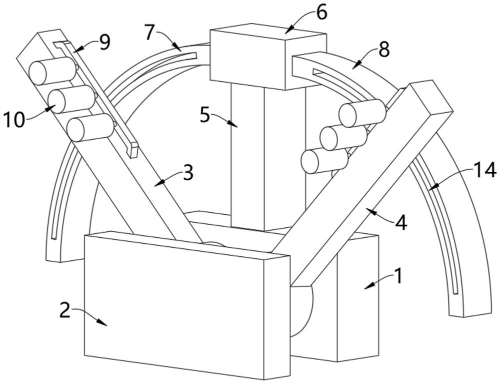
[0053] see Figure 1-Figure 5 , a tendon stretcher for physical exercise, comprising a base plate 1 and a seat plate 2, a first swing arm 3 and a second swing arm 4 are movable between the base plate 1 and the seat plate 2, the first swing arm 3 and the second swing arm The arms 4 are arranged in a figure-eight shape, the body of the athlete or user sits on the seat board 2, and both legs are respectively placed on the first swing arm 3 and the second swing arm 4;

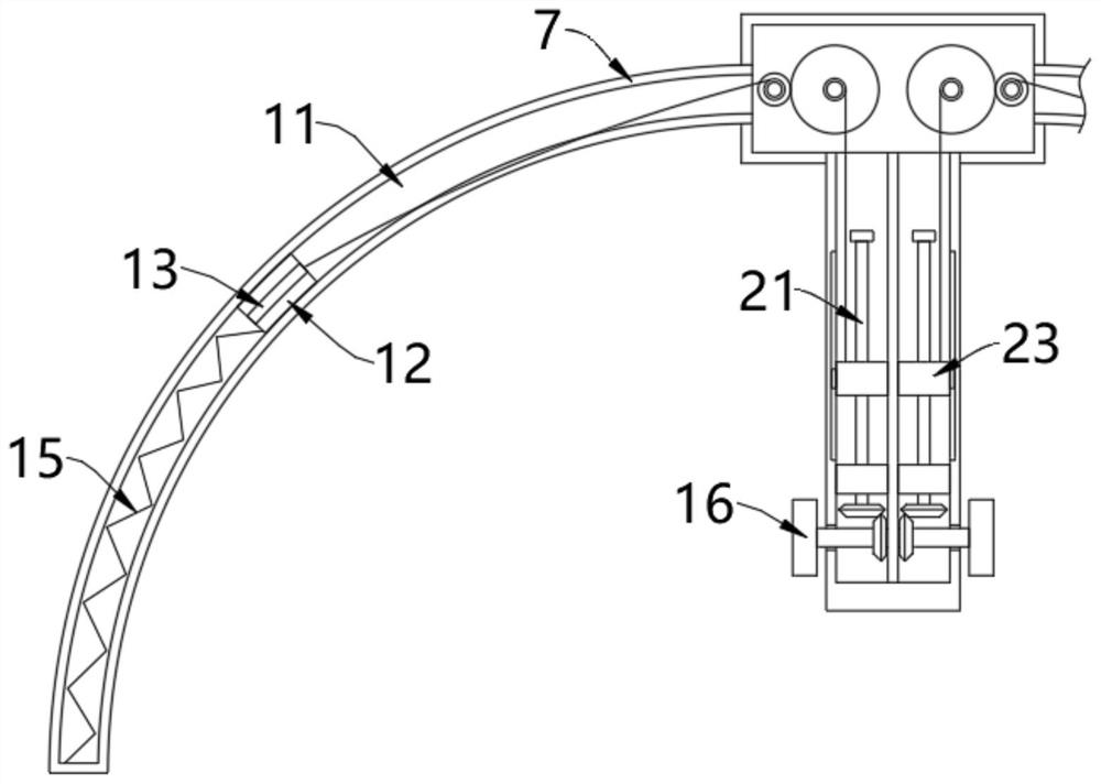
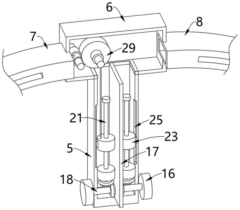
[0054] The outer wall of base plate 1 is fixedly installed with connecting cabinet 5, and the top of connecting cabinet 5 is fixedly installed with control box 6, and the left and right sides of control box 6 are respectively fixedly installed with first curved cabinet 7 and second curved cabinet 8, the first The interior of the curved cabinet 7 and the second curved cabinet 8 is formed with an inner cavity 11, and the inner walls of the two inner cavities 11 are all slidably provided with a slider 12, and the outw...

Embodiment 2

[0069] see Figure 6 and Figure 7 , on the basis of Embodiment 1, the outer walls of the first swing arm 3 and the second swing arm 4 are provided with a fixed frame 9 on the opposite side, and a plurality of retaining wheels 10 are rotated on the fixed frame 9, and on the fixed frame 9 The blocking wheel 10 plays a blocking role. When the athlete's legs are placed on the first swing arm 3 and the second swing arm 4, the blocking wheel 10 can block the athlete's legs, so that the athlete's legs can be effectively stretched. Open, do stretching exercises;

[0070] Both ends of the fixed frame 9 are fixedly equipped with pull rods 34, and the ends of the pull rods 34 are fixedly equipped with pull plates 35. The pull plate 35 is movably arranged inside the plate groove 36, and the plate groove 36 is opened on the first swing arm 3 and the second swing arm. Inside the arm 4, a first spring 37 is also provided between the top of the pull plate 35 and the inner top wall of the p...

Embodiment 3

[0073] see Figure 8 and Figure 9 , on the basis of Embodiment 1 or Embodiment 2, the bottom ends of the first swing arm 3 and the second swing arm 4 are fixedly equipped with a rotating ring 38, and the rotating ring 38 is rotatably arranged on the bottom plate 1, and the inside of the rotating ring 38 A tapered groove 39 is formed, and the inner wall of the tapered groove 39 is movably provided with a tapered column 40. The top of the tapered column 40 is fixedly connected with the seat plate 2, and the bottom of the tapered column 40 is fixedly equipped with a pressing plate 41, which is movable. In the inside of the vertical groove 42, the vertical groove 42 is opened in the inside of the base plate 1, and a second spring 43 is arranged between the bottom of the pressing plate 41 and the inner bottom wall of the vertical groove 42. When the athlete is not sitting on the seat plate 2, the seat plate 2 and the conical column 40 are pushed out by the second spring 43, and t...


PUM


Abstract

The invention relates to the technical field of stretching devices, and discloses a stretching device for physical exercise, which comprises a bottom plate and a seat plate, a first swing arm and a second swing arm are movably arranged between the bottom plate and the seat plate, the first swing arm and the second swing arm are arranged in a splayed shape, a connecting cabinet is fixedly mounted on the outer wall of the bottom plate, a control box is fixedly installed at the top of the connecting cabinet, and a first arc-shaped cabinet and a second arc-shaped cabinet are fixedly installed on the left side and the right side of the control box correspondingly. When tendon stretching is needed, an athlete sits on the seat plate, the two legs of the athlete are placed on the first swing arm and the second swing arm respectively, the athlete controls rotation of the two rotary knobs with hands to enable the first swing arm and the second swing arm to swing respectively, and therefore tendon stretching can be freely conducted, the first swing arm swings to enable the left leg to be opened, the second swing arm swings to enable the right leg to be opened, the two legs can also be stretched at the same time, the tendon stretching effect is better, use is more convenient, and the upper half body does not need to do large-amplitude actions.

Description

technical field [0001] The invention relates to the technical field of tendon stretching devices, in particular to a tendon stretching device for physical exercise. Background technique [0002] In order to prevent sudden movement from causing ligament strain, it is necessary to perform stretching exercises before sports. In the prior art, athletes usually place their legs on a higher platform when performing stretching, and the other leg Support, and then perform stretching exercises, but this method supports the body with one leg during stretching, which will not only increase the difficulty of stretching, reduce the efficiency of stretching, but also easily stand unstable and fall, resulting in injury ; There are also some athletes who press the legs by the way of the step, but the effect of the leg press is poor, and it is difficult to fully stretch the tendons; [0003] The Chinese patent announcement number is: the invention patent of CN110124271B, which provides a ki...

Claims


Application Information

Patent Timeline
Patent Type & Authority Applications(China)
IPC IPC(8): A63B23/04A63B21/05
CPCA63B23/04A63B21/05
Inventor 张晓靖吴俊茂
Owner 张晓靖
Why Eureka
Try Eureka