Self-expansion anchor rod device with displacement monitoring function

A displacement monitoring and self-expansion technology, which is used in the testing of foundation structures, sheet pile walls, buildings, etc., can solve the problems of easy damage, failure, and failure of the anchoring agent at the stress point of the anchor, so as to increase the service life and adaptability. wide effect

Active Publication Date: 2022-02-01
NORTH CHINA UNIV OF WATER RESOURCES & ELECTRIC POWER +1
View PDF3 Cites 0 Cited by
  • Summary
  • Abstract
  • Description
  • Claims
  • Application Information

AI Technical Summary

Problems solved by technology

[0007] In view of the above situation, in order to overcome the defects of the prior art, the present invention provides a self-expanding bolt device with displacement monitoring, which effectively solves the problems of the prior art The stress point of the bolt in the middle is easy to be damaged on the outside, which eventually leads to poor bolt effect or even failure, the problem that the anchoring agent of the anchor head is easy to fail, and the problem that rock mass deformation cannot be monitored at different levels

Method used


Image

  • Self-expansion anchor rod device with displacement monitoring function
  • Self-expansion anchor rod device with displacement monitoring function
  • Self-expansion anchor rod device with displacement monitoring function

Examples


Embodiment 1

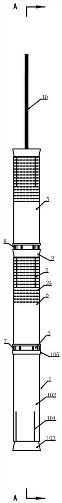
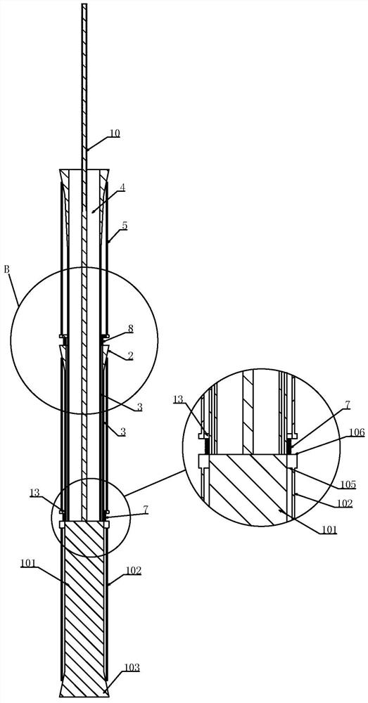
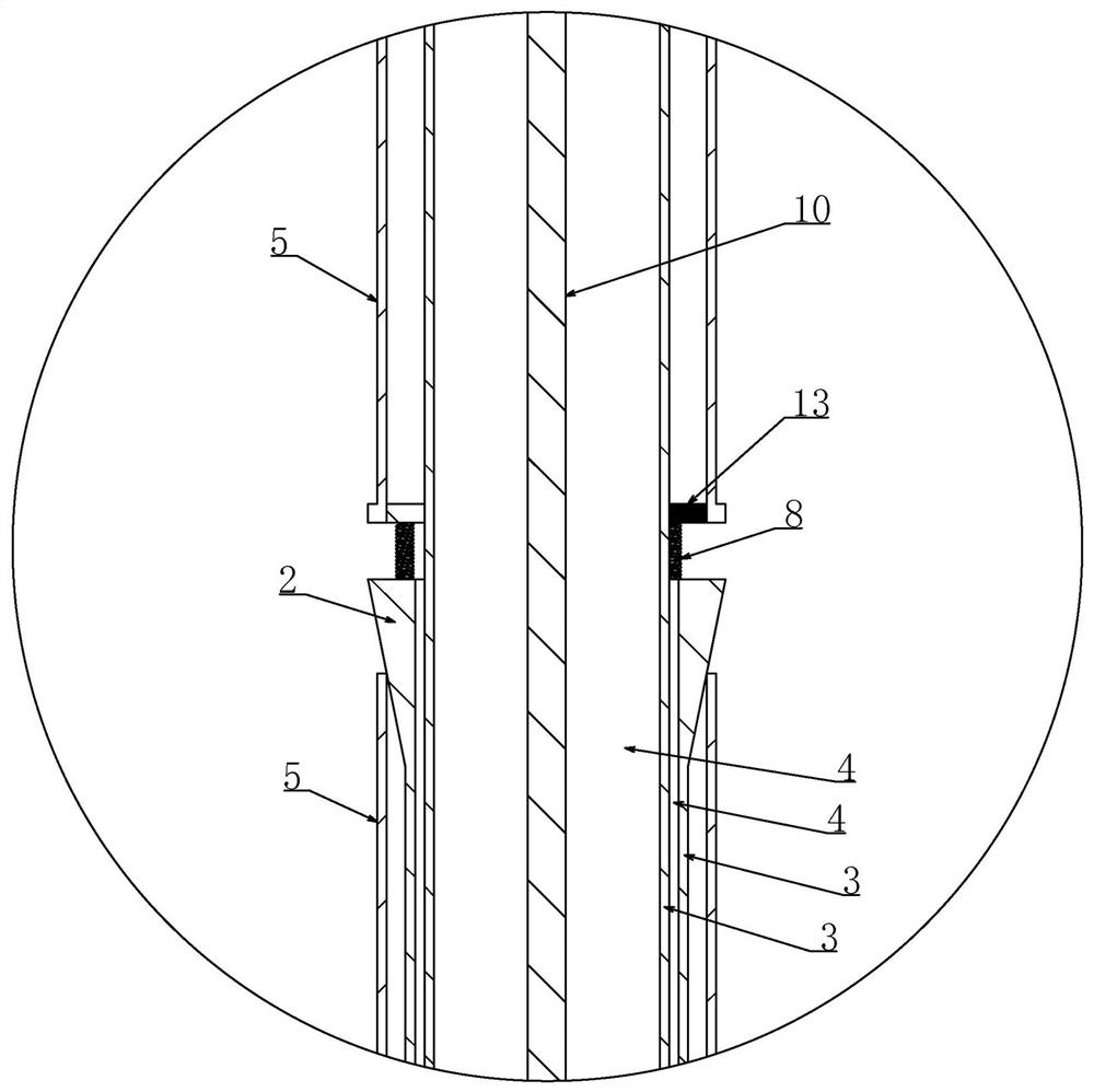
[0035] Embodiment 1, the technical solution is a self-expanding anchor device with displacement monitoring, including an anchoring end 1, characterized in that, the anchoring end 1 is arranged axially outwardly with a plurality of axially outwardly spaced Inner small frustum 2, the axial inner end of the frustum 2 is coaxially connected with a tension body 3, and the axial outer end of the frustum 2 is provided with a through hole that penetrates the tension body 3 axially inward 4. The tension body 3 at the innermost end in the axial direction is fixed on the anchoring end 1, and the tension body 3 at the axial outer side passes through the conical frustum body 2 and the through hole 4 in the tension body 3 adjacent to the axial inner side. On the anchoring end 1, the axially inner part of the circular frustum body 2 is covered with a sleeve 5 whose axial inner end is slidingly sleeved on the tension body 3, and the axially outer end of the sleeve 5 is provided with a pluralit...

Embodiment 2

[0048] Embodiment 2, on the basis of Embodiment 1, a screw 10 is fixed at the center of the anchoring end 1, and the screw 10 passes through the through hole 4 in the axially outermost conical body 2 toward the axially outward, and the A tray 11 is sheathed on the portion of the screw 10 passing through the outermost conical body 2 in the axial direction, and a nut 12 is screwed on the screw 10 on the axial outer side of the tray 11 .

[0049] A third through hole 22 may be opened on the tray 11 in this embodiment, and the lead wire of the displacement sensor is led out from the third through hole 22, so as to be installed on the wireless signal transmitting device outside the anchor hole.

[0050] In this embodiment, a screw rod 10 is added, which is a conventional anchoring method, and one more level of protection can be set according to the situation. The screw rod 10 is fixed at the center of the anchor end 1, and then the axial outer end of the screw rod 10 extends out to ...

Embodiment 3

[0051] Embodiment 3, on the basis of Embodiment 1, the anchoring end 1 is anchored at the axial inner end of the anchor hole 9, and the side wall of the sleeve 5 on the axial inner side of the slot 6 is anchored in the anchor hole 9, so The inner wall of the anchor hole 9 at the groove 6 is attached to the sleeve pipe 5 .

[0052] It is arranged in this way that when the side wall of the anchor hole 9 moves, the sleeve pipe 5 has a tendency to move axially outward, and the sleeve pipe 5 cooperates with the frustum 2 so that the sleeve pipe 5 has a tendency to open axially to the outside. Clinging to the side wall of the anchor hole 9, the increased expansion force prevents the side wall of the anchor hole 9 from moving outward in the axial direction. The fixation between the pipe 5 and the anchor hole 9 breaks during the movement of the rock mass, resulting in failure of the entire anchorage.


PUM


Abstract

The invention provides a self-expansion anchor rod device with a displacement monitoring function. The problems that an existing anchor rod is insufficient in force bearing point, the force bearing point of an anchoring section is prone to being damaged, finally, the effect of the anchor rod is poor, and rock mass deformation cannot be monitored at different levels are solved. The lower end of each sleeve is connected with one end of a displacement sensor, the other end of the displacement sensor on the sleeve at the lowest end is connected to an anchoring end, the other ends of the other displacement sensors are connected to the end face of an adjacent circular truncated cone, a first through hole is formed in the sleeve on one side of each displacement sensor, and a second through hole is formed in the axial outer portion of each sleeve. The device further comprises a wireless signal transmitting device. A wire of each displacement sensor sequentially passes through the first through hole of the sleeve at the axial outer end of the displacement sensor, an inner cavity of the sleeve and the second through hole to be connected to the wireless signal transmitting device. The self-expansion anchor rod device further comprises a wireless signal receiving device used for receiving signals of the wireless signal transmitting device. The wireless signal receiving device is connected with a monitoring host.

Description

technical field [0001] The invention relates to anchor rods, in particular to a self-expanding anchor rod device with displacement monitoring. Background technique [0002] Anchor rods are widely used in slope treatment engineering, and their main function is to control surface engineering such as slopes and deep foundation pits, as well as underground chambers such as tunnels and stopes. [0003] In some surrounding rocks with relatively low grades, such as in soft rock areas, large deformations often occur in surrounding rocks, and under the action of earthquakes, large deformations often occur in some surrounding rocks. Large deformation factors also include loads, etc., and the number of bolts used as surrounding rock support structures is the largest and most widely used in work. [0004] Most of the rigid anchor rods in the prior art only directly anchor one end of the anchor rod to the bottom of the anchor hole, and then press the tray on the outer side of the slope ...

Claims


Application Information

Patent Timeline
Patent Type & Authority Applications(China)
IPC IPC(8): E02D5/74E02D5/76E02D33/00
CPCE02D5/74E02D5/76E02D33/00E02D2200/146E02D2600/10E02D2600/30Y02A10/23
Inventor 张兴胜林社杰于刚张瑞芳胡梦柯姜彤董金玉李永生王旭
Owner NORTH CHINA UNIV OF WATER RESOURCES & ELECTRIC POWER
Why Eureka
Try Eureka