Self-compensation type electrified wire connection integrated installation device

An installation device and self-compensation technology, applied in the direction of cable suspension device, overhead line/cable equipment, etc., can solve the problems of thread locking, actual cable clamp operation trouble, failure of cable clamp parallel groove, etc., to achieve reliable clamping holding effect

Pending Publication Date: 2022-02-01
HEFEI CAS LANRUI TECH CO LTD
View PDF0 Cites 1 Cited by
  • Summary
  • Abstract
  • Description
  • Claims
  • Application Information

AI Technical Summary

Problems solved by technology

Once the cable clamp shakes during the working process of the striking part, the assembly efficiency will be lower if it is light, and the tension nut and the tension bolt will be produced because the screw sleeve cannot continue to drive the tension nut to rotate, or the tension nut and the tension bolt will be generated due to the strain of the force clamp. The problem of thread locking between them, etc., resulting in the failure of the clamp and groove
In addition, when the tension nut rotates upward along the tension bolt, the tension nut will gradually break away from the relatively fixed screw sleeve, which will cause incomplete contact between the screw sleeve and the tension nut
The above-mentioned incomplete contact phenomenon will not only make the assembly process of the J-shaped clamp inefficient, but also need to start and stop frequently to hit the motor many times in order to ensure the tension nut to rotate; it is also easy to continue to drive the tension nut due to the screw sleeve As a result, the clamping force of the wire clamp is low or even the groove fails.
Regardless of the above-mentioned situations, operators have to manually work at heights to troubleshoot, which is extremely time-consuming and labor-intensive, which obviously brings great trouble to the actual line clip and ditch operation.

Method used


Image

  • Self-compensation type electrified wire connection integrated installation device
  • Self-compensation type electrified wire connection integrated installation device
  • Self-compensation type electrified wire connection integrated installation device

Examples


Embodiment Construction

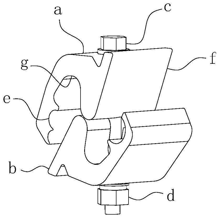
[0056] For ease of understanding, combined here Figure 1-13 , taking the installation and construction of the traditional J-shaped clamp (hereinafter referred to as the clamp) as an example, the specific structure and working method of the present invention are further described as follows:

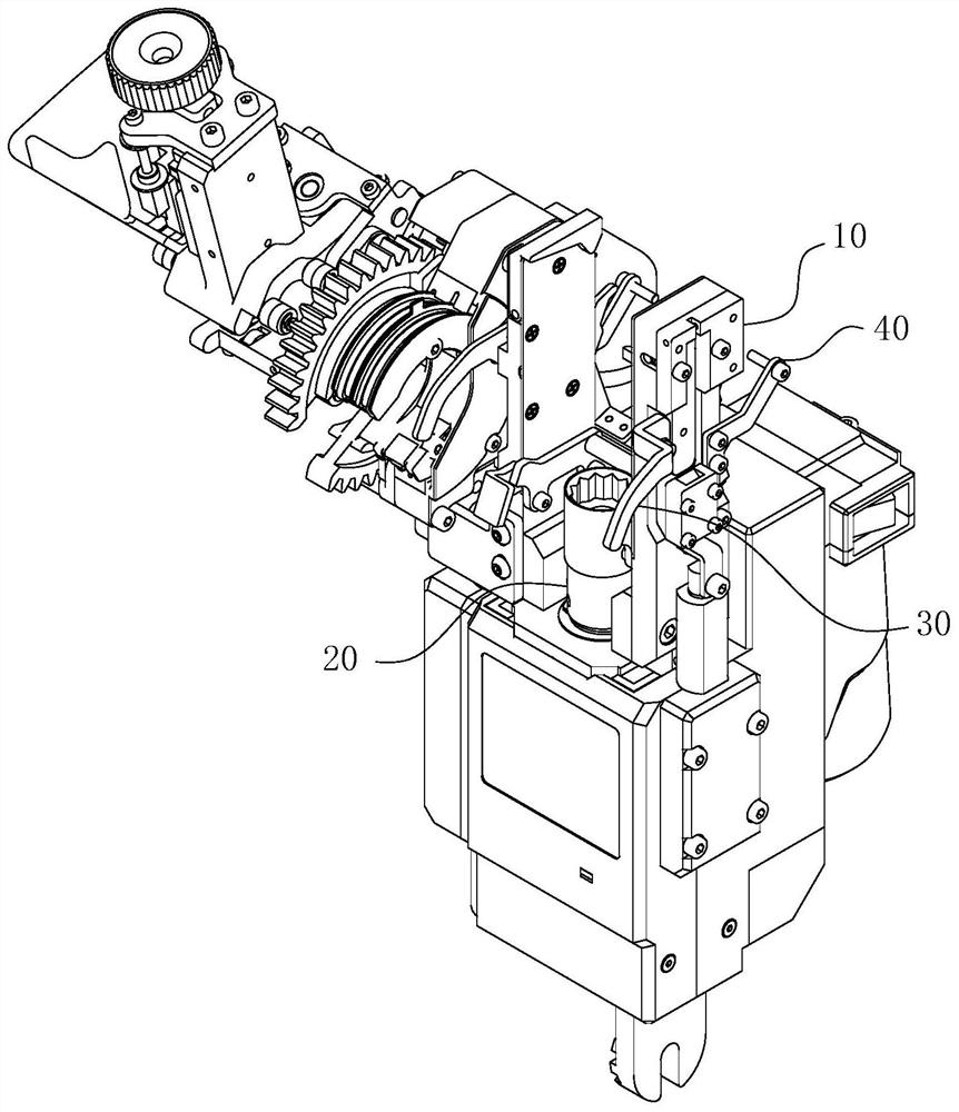
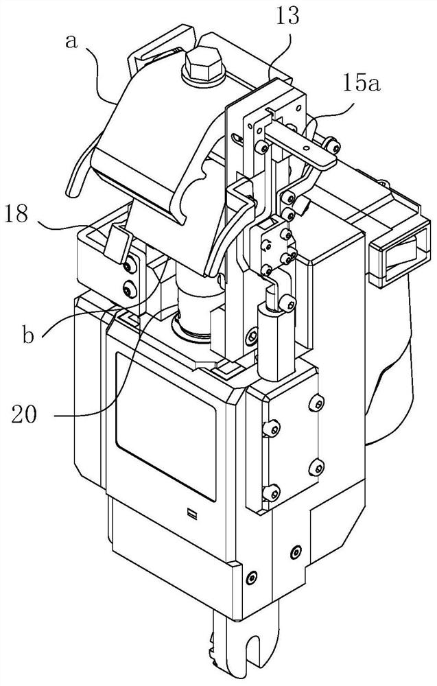
[0057] The present invention can be used in remote control equipment such as robots; during actual assembly, the present invention can be fixed on the mechanical arm. At this time, since the main line is fixed as a reference object, the present invention can be lifted by the mechanical arm to complete the relative main line. The hook-type parallel ditch operation.

[0058] During the actual work of the present invention, its concrete structure is as Figure 2-13 As shown, its main structure includes a positioning installation part 10 for fixing the wire clip, a striking part 20, a secondary wire locking clip 40 for fixing the secondary wire B, and a main wire guiding clip 30 for loading...


PUM


Abstract

The invention belongs to the technical field of power equipment, and relates to a self-compensation type electrified wire connection integrated installation device. The device comprises a positioning assembly used for fixing an upper guide block at a wire clamp, the positioning assembly comprises an ascending limiting block used for limiting ascending of the upper guide block and a descending limiting block used for limiting descending of the upper guide block, and the ascending limiting block and the descending limiting block are both horizontally hinged to a clamping rod; the hinge axes of the ascending limiting block and the descending limiting block are parallel to each other, and the hinge points of the ascending limiting block and the descending limiting block spatially avoid the plugging path of the wire clamp; a striking part comprises a screw sleeve used for screwing a tightening nut at the wire clamp, and the screw sleeve is driven by a striking motor to generate coaxial rotation action; and the striking part further comprises a compensation assembly which is used for driving the screw sleeve to generate axial approaching motion relative to the tightening nut while the screw sleeve generates the rotation motion. According to the self-compensation type electrified wire connection integrated installation device of the invention, the accuracy, the stability and the efficiency of the parallel groove of the wire clamp can be effectively guaranteed.

Description

technical field [0001] The invention belongs to the technical field of electric power equipment, and in particular relates to a self-compensating integrated installation device for electrification and fire connection. Background technique [0002] The J-shaped clamp is a non-load-bearing link clamp, which is used to connect the secondary line of the branch line of the 10kV power line to the main line of the main line. The shape reference of the J-shaped clamp figure 1 As shown, it includes two interlocking J-shaped guide blocks and a tension bolt c and a tension nut d that guide the two guide blocks to produce similar movements. During installation, the notch e at the head end of the upper guide block a is embedded with the auxiliary line B of the branch line, and the notch e at the head end of the lower guide block B is embedded with the main line A of the trunk line; The two guide blocks are tightened by the cooperation of the nut d, so that the auxiliary line B and the ...

Claims


Application Information

Patent Timeline
Patent Type & Authority Applications(China)
IPC IPC(8): H02G1/02H02G7/05
CPCH02G1/02H02G7/05
Inventor 孙丙宇姚德亮郭兴源孙璞
Owner HEFEI CAS LANRUI TECH CO LTD
Why Eureka
Try Eureka