Self-compensation type wire clamp installation system for J-shaped wire clamp

An installation system and self-compensation technology, which is applied in the direction of cable installation, cable installation device, equipment for removing/armouring cables, etc., can solve the problems of increased design difficulty, dislocation lock, complex structure, etc., and achieve reliable and stable use, Effect of reliable clamping and ensuring positional stability

Pending Publication Date: 2022-02-08
HEFEI CAS LANRUI TECH CO LTD
View PDF0 Cites 0 Cited by
  • Summary
  • Abstract
  • Description
  • Claims
  • Application Information

AI Technical Summary

Problems solved by technology

There is a common defect in the peeling devices currently on the market, that is, the two sets of clamping blocks that constitute the clamping part are reciprocating in a straight line toward or away from each other, which leads to the following problems: On the one hand, the clamping blocks of the straight travel need Larger movable space to complete the action, which makes it necessary to reserve a larger space for the action of the clamping part during design, which makes the design more difficult and the structure more complicated. At the same time, the volume of the whole machine is generally smaller Large, not conducive to semi-automatic or even fully automatic operation
On the other hand, because the stripper relies on the matching of the grooves on the adjacent surfaces of the two sets of clamping blocks to bite the cable, the two sets of clamping blocks of the straight stroke have no self-correcting properties, so when the two sets of clamping blocks When the cable is clamped by the holding block, it is easy to be crooked due to the improper placement of the cable, and even the power system at the clamping part is dislocated and locked, which brings many troubles to the construction site

Method used


Image

  • Self-compensation type wire clamp installation system for J-shaped wire clamp
  • Self-compensation type wire clamp installation system for J-shaped wire clamp
  • Self-compensation type wire clamp installation system for J-shaped wire clamp

Examples


Embodiment Construction

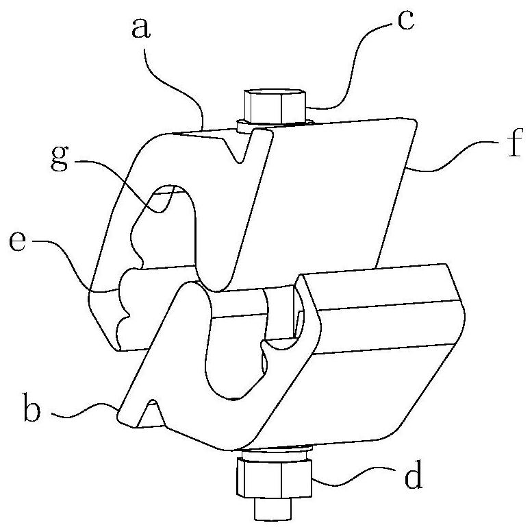
[0064] For ease of understanding, combined here Figure 1-17 , taking the installation and construction of traditional J-type wire clips (hereinafter referred to as wire clips) as an example, the concrete structure and working method of the present invention are further described as follows:

[0065] The present invention can be used in remote control equipment such as robots; during actual assembly, the present invention can be fixed on the mechanical arm. At this time, since the main line is fixed as a reference object, the present invention can be lifted by the mechanical arm to complete the relative main line. The hook-type parallel ditch operation.

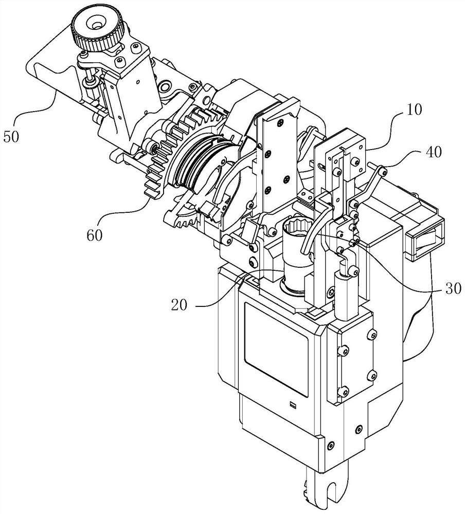
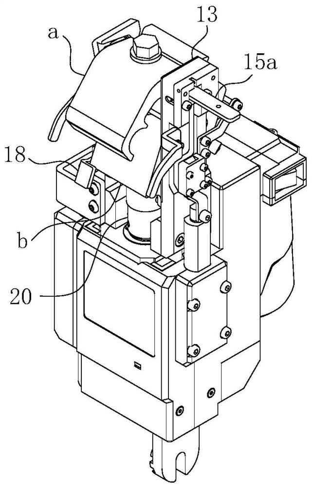
[0066] During the actual work of the present invention, its concrete structure is as Figure 2-17 As shown, it is divided into a stripper and a clamp installer located behind the stripper; when it is necessary to operate figure 2 In the structure shown, the cable is first clamped and stripped by the stripper, and then the ...


PUM


Abstract

The invention belongs to the technical field of power equipment, and particularly relates to a self-compensation type wire clamp installation system for a J-shaped wire clamp. A striking part and a positioning assembly are arranged at a positioning mounting part, the positioning assembly comprises an ascending limiting block and a descending limiting block, and the ascending limiting block and the descending limiting block are both horizontally hinged to a clamping rod; the upward limiting block generates a hinging action from top to bottom and is pressed on the upper surface of the upper guide block; and the downward limiting block generates a hinging action from bottom to top and is propped against the middle-section notch of the upper guide block. The system further comprises a fixing frame, an upper clamping block and a lower clamping block, and the hinge axes of the upper clamping block and the lower clamping block are parallel to each other or coincide with each other. The system further comprises a power end which is used for driving the two groups of clamping blocks to generate hinged opening and closing actions along the tail end hinged seat. According to the invention, the position stability of the wire clamp in the whole parallel groove process and the stripping reliability of the cable can be ensured, and finally, an effective guarantee is provided for improving the parallel groove accuracy, stability and efficiency of the wire clamp.

Description

technical field [0001] The invention belongs to the technical field of power equipment, and in particular relates to a self-compensating clamp installation system for J-shaped clamps. Background technique [0002] The J-shaped clamp is a non-load-bearing link clamp, which is used to connect the secondary line of the branch line of the 10kV power line to the main line of the main line. The shape reference of the J-shaped clamp figure 1 As shown, it includes two interlocking J-shaped guide blocks and a tension bolt c and a tension nut d that guide the two guide blocks to produce similar movements. During installation, the notch e at the head end of the upper guide block a is embedded with the auxiliary line B of the branch line, and the notch e at the head end of the lower guide block B is embedded with the main line A of the trunk line; The two guide blocks are tightened by the cooperation of the nut d, so that the auxiliary line B and the main line A are clamped on the two...

Claims


Application Information

Patent Timeline
IPC IPC(8): H02G1/14H02G1/12
CPCH02G1/14H02G1/1265
Inventor 孙丙宇孙璞郭兴源姚德亮
Owner HEFEI CAS LANRUI TECH CO LTD
Why Eureka
Try Eureka