Mobile video monitoring camera device

A technology of video monitoring and camera devices, which is applied in the field of mobile video monitoring and camera devices, can solve the problems that the installation position cannot be adjusted, is fixed, and the blind area of ​​the video monitoring camera monitoring field is large, so as to facilitate replacement and maintenance and reduce installation Speed, reducing the effect of blind spots in the field of vision

Inactive Publication Date: 2022-02-01
深圳市有为晟科技有限公司
View PDF0 Cites 4 Cited by
  • Summary
  • Abstract
  • Description
  • Claims
  • Application Information

AI Technical Summary

Problems solved by technology

[0002] Surveillance camera devices are mainly used as quasi-cameras in security. Its pixel and resolution are higher than those of computer video heads and lower than professional digital cameras; surveillance camera devices are widely used in schools, companies, banks, transportation, safe cities, etc. Multiple security areas; surveillance camera devices are mostly single video capture devices, and rarely have the function of data storage. Surveillance camera devices need to be installed in high places, such as walls and utility poles
[0003] At present, when the existing monitoring camera devices are in use, there are usually the following deficiencies: 1. The installation position of the existing monitoring camera devices is usually fixed, and the installation position cannot be adjusted, thereby reducing the scope of video monitoring camera shooting. The visual field blind area of ​​camera monitoring is bigger, has reduced the use effect of video monitoring camera; 2, existing monitoring camera device can not carry out fast installation and disassembly to mobile video monitoring camera device, thereby increased the speed of monitoring camera device installation, and Not conducive to the replacement and maintenance of surveillance camera devices

Method used


Image

  • Mobile video monitoring camera device
  • Mobile video monitoring camera device
  • Mobile video monitoring camera device

Examples


Embodiment Construction

[0029] The embodiments of the present invention will be described in detail below with reference to the accompanying drawings, but the present invention can be implemented in many different ways defined and covered by the claims.

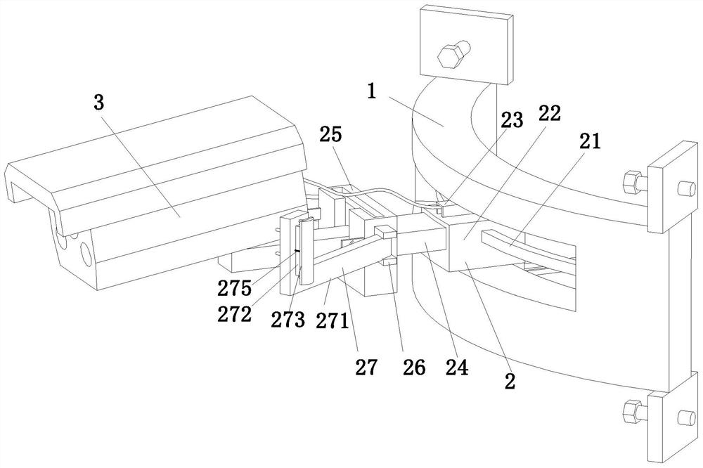
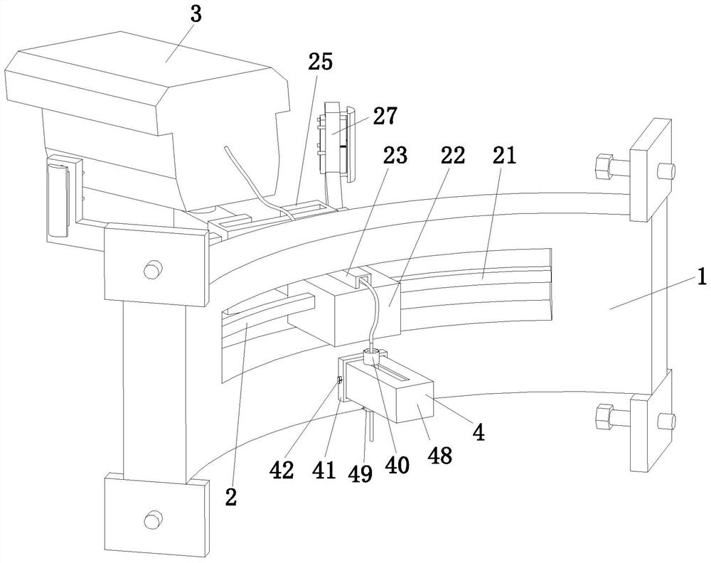
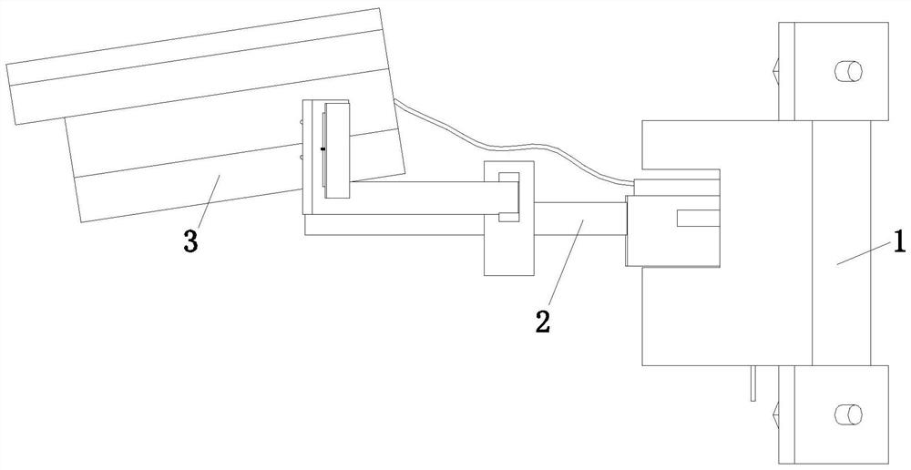
[0030] refer to figure 2, a mobile video surveillance camera device, including a mounting plate 1, a connecting mechanism 2, a camera module 3 and a wire storage mechanism 4, the mounting plate 1 is in an arc-shaped structure, and a sliding through hole is opened in the middle of the mounting plate 1, A connecting mechanism 2 is connected inside the sliding through hole, a camera module 3 is plugged into the left end of the connecting mechanism 2, and a cable storage mechanism 4 is installed in the middle and lower part of the right end of the mounting plate 1.

[0031] refer to figure 1 , the upper and lower ends of the mounting plate 1 are symmetrically installed with fixed plates, and the middle part of the fixed plate is threadedly connected w...


PUM


Abstract

The invention relates to the technical field of safety protection, in particular to a mobile video monitoring camera device, which comprises a mounting plate, a connecting mechanism, a camera module and a wire storage mechanism, wherein the mounting plate is of an arc-shaped structure, a sliding through hole is formed in the middle of the mounting plate, the connecting mechanism is connected into the sliding through hole, and the camera module is inserted into the left end of the connecting mechanism. In the prior art, when an existing monitoring camera device is used, the installation position is usually fixed and cannot be adjusted, so that the shooting range of a video monitoring camera is reduced, the blind area of the field of view monitored by the video monitoring camera is large, and the use effect of the video monitoring camera is reduced. According to the invention, the problems in the prior art can be solved; and according to the mobile video monitoring camera device provided by the invention, the adopted connecting mechanism can be used for adjusting the mounting position, so that the shooting range of the video monitoring camera is enlarged, and the use effect of the video monitoring camera is improved.

Description

technical field [0001] The invention relates to the technical field of safety protection, in particular to a mobile video surveillance camera device. Background technique [0002] Surveillance camera devices are mainly used as quasi-cameras in security. Its pixel and resolution are higher than those of computer video heads and lower than professional digital cameras; surveillance camera devices are widely used in schools, companies, banks, transportation, safe cities, etc. Multiple security areas; surveillance camera devices are mostly single video capture devices, and rarely have data storage functions. Surveillance camera devices need to be installed in high places, such as walls and utility poles. [0003] At present, when the existing monitoring camera devices are in use, there are usually the following deficiencies: 1. The installation position of the existing monitoring camera devices is usually fixed, and the installation position cannot be adjusted, thereby reducing ...

Claims


Application Information

Patent Timeline
Patent Type & Authority Applications(China)
IPC IPC(8): H04N5/225F16M11/04F16M13/02H02G3/02
CPCF16M11/045F16M11/041F16M13/02H02G3/02H04N23/50
Inventor 李多
Owner 深圳市有为晟科技有限公司
Why Eureka
Try Eureka