Lidar optical structure and lidar device

A technology of laser radar and optical structure, applied in the direction of measurement device, electromagnetic wave re-radiation, utilization and re-radiation, etc., can solve the problem of low utilization rate of laser beam energy, and achieve the effect of improving utilization efficiency

Pending Publication Date: 2018-08-10
成都楼兰科技有限公司
View PDF0 Cites 13 Cited by
  • Summary
  • Abstract
  • Description
  • Claims
  • Application Information

AI Technical Summary

Problems solved by technology

[0004] The purpose of the present invention is to provide a laser radar optical structure to solve the problem of low energy utilization of existing laser beams

Method used


Image

  • Lidar optical structure and lidar device
  • Lidar optical structure and lidar device
  • Lidar optical structure and lidar device

Examples


no. 1 example

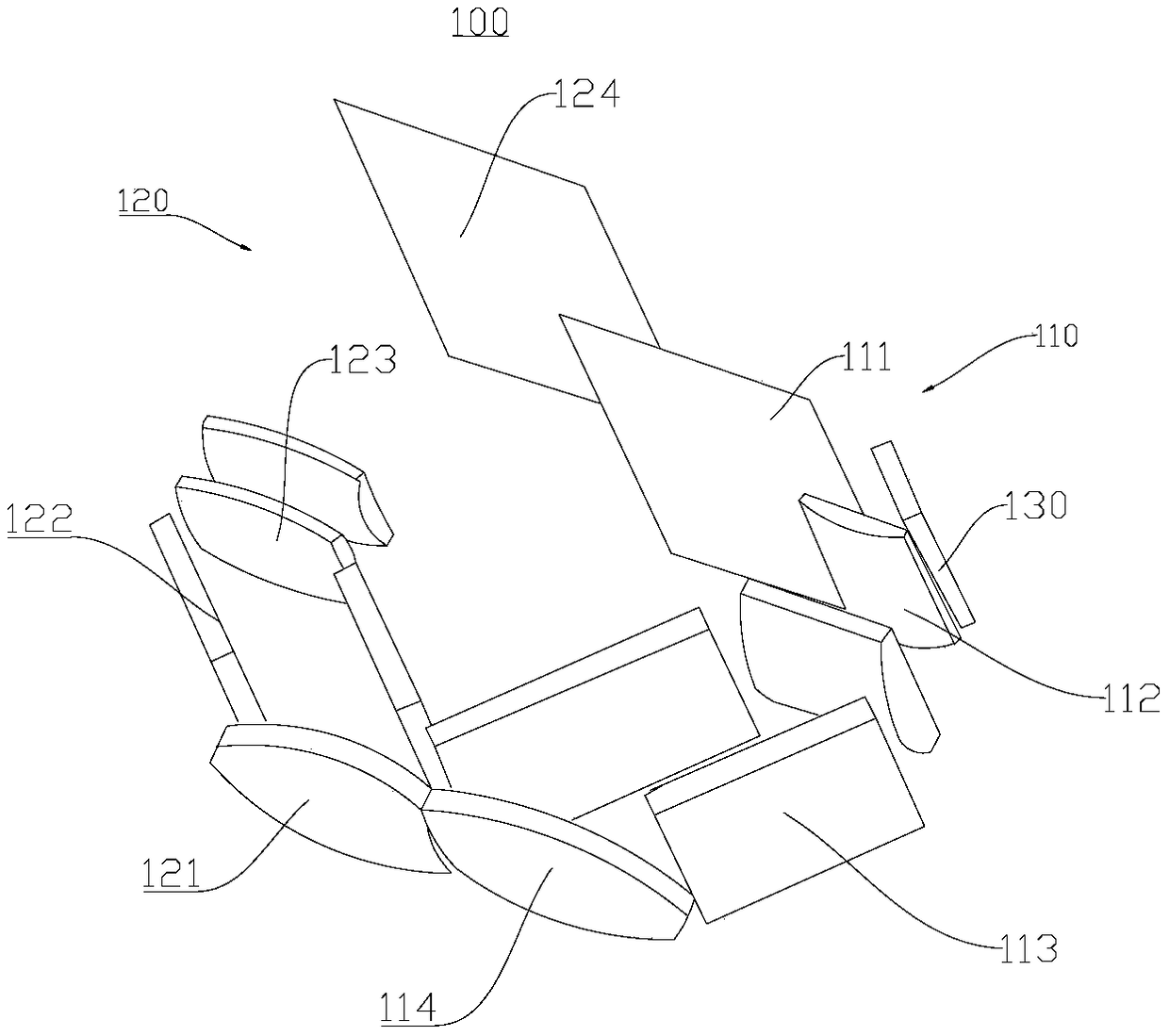
[0055] Please refer to figure 1 and figure 2 , this embodiment provides a lidar optical structure 100 , which includes a transmitting device 110 and a receiving device 120 .

[0056] Further, the emitting device 110 includes a laser emitting mechanism 111 , a collimating lens group 112 , a first optical path deflecting assembly 113 and an optical path emitting assembly 114 .

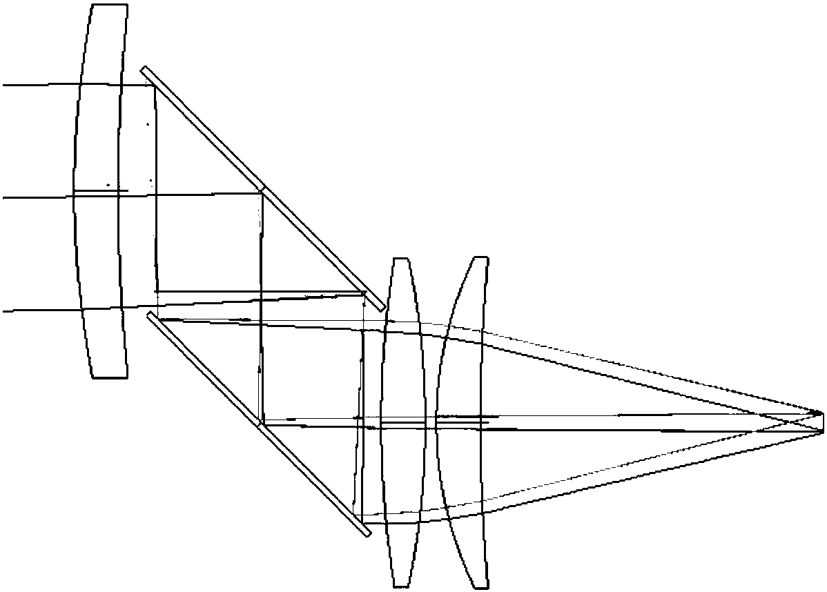
[0057] Further, after the laser emitting mechanism 111 emits the laser beam, the collimating lens group 112 collimates the laser beam, and the collimated laser beam passes through the first optical path deflection component 113, so that the laser beam is integrated into one In the channel, it provides a favorable guarantee for the subsequent use of the laser beam in the channel to scan the object.

[0058]Further, a third optical path bend 130 is provided on one side of the laser emitting mechanism 111 .

[0059] By setting the third optical path bend 130, the light beam emitted by the laser emitting...

no. 2 example

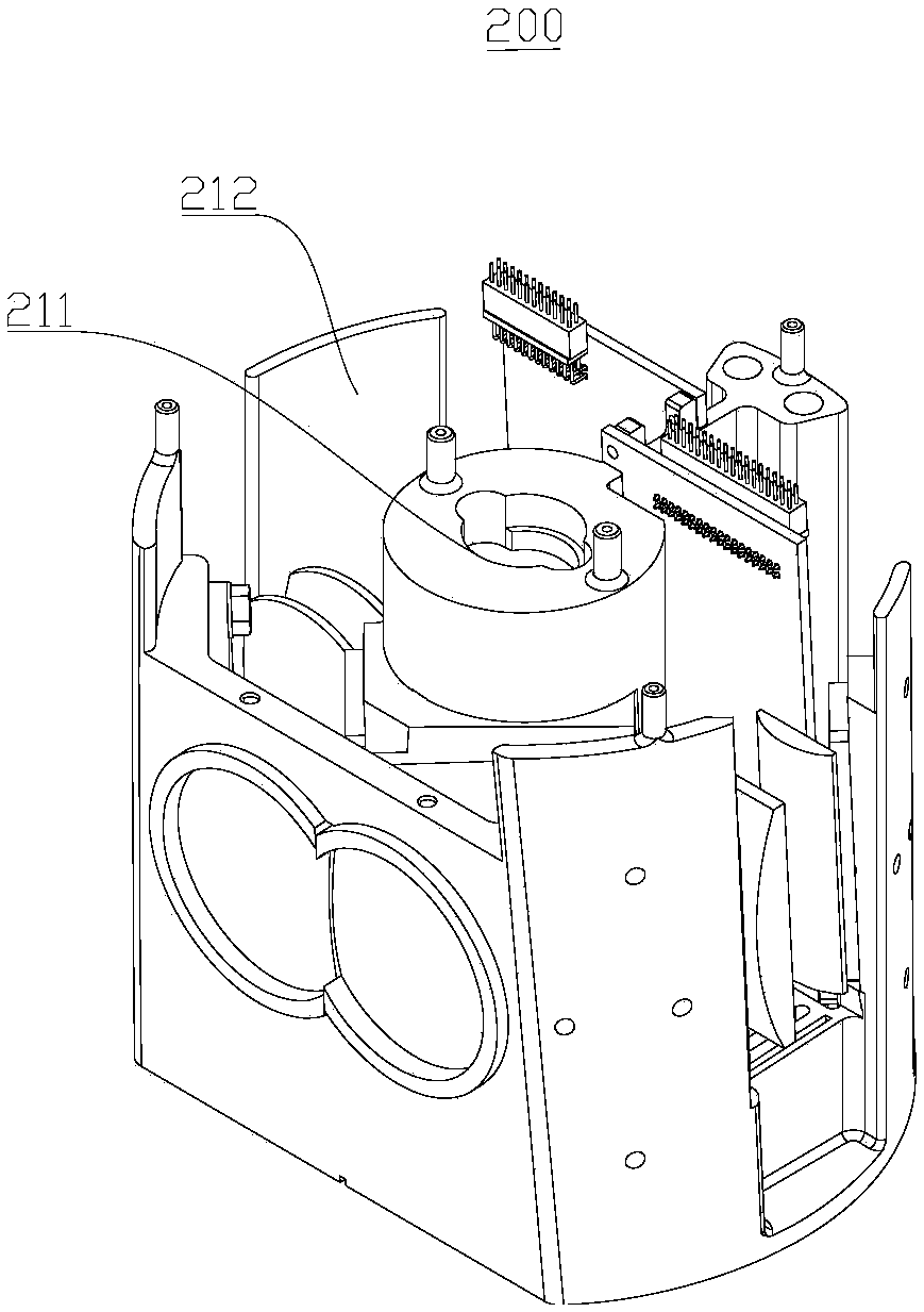
[0102] Please refer to image 3 and Figure 4 , this embodiment provides a laser radar device 200, and the laser radar device 200 includes the laser radar optical structure and the turntable provided in the first embodiment.

[0103] Further, the turntable includes a drive mechanism 211 and a turntable body 212; the drive mechanism 211 is transmission-connected to the turntable body 212; the drive mechanism 211 is configured to drive the turntable body 212 to rotate, and during the rotation, the laser radar optical structure scans the surrounding object.


PUM


Abstract

The invention relates to the field of photoelectric equipment and particularly relates to a lidar optical structure and a lidar device. The structure comprises a transmitting device and a receiving device, wherein the transmitting device comprises a laser transmitting mechanism, a collimating lens group, a first optical path turning assembly and an optical path emitting assembly; the receiving device comprises an optical path receiving assembly, a second optical path turning assembly, a light gathering assembly and a laser receiving mechanism; the collimating lens group is used for collimatingdivergent laser beams transmitted by the laser transmitting mechanism to parallel laser beams; and the first optical path turning assembly and the second optical path turning assembly are used for turning the parallel laser beams to a channel. According to the structure of the invention, through a new method of adopting the collimating lens group for collimation and receiving, the difficult problem of alignment in the prior art is overcome, collimation of the laser in two directions is realized, the utilization efficiency of light energy is greatly improved, the parallel laser beams after being collimated and emergent can cover a range of dozens of degrees, and the detection range is large enough.

Description

technical field [0001] The invention relates to the field of optoelectronic equipment, in particular to a laser radar optical structure and a laser radar device. Background technique [0002] In recent years, the development of autonomous driving is in full swing, and lidar is the core part of autonomous driving. Generally speaking, the optical part of the radar is divided into two parts, the transmitting end and the receiving end, and the transmitting end involves the collimation of the laser beam to obtain the maximum efficiency so that the radar can detect as far away as possible. The laser beam is received by the receiving end to indicate that there is an obstacle ahead. The signal processing system constructs the spatial model of the obstacle and calculates its moving speed based on the feedback information. In order to obtain higher spatial resolution, scanning and multi- Road laser method, so that more spatial information can be obtained in a short period of time to ...

Claims


Application Information

Patent Timeline
Patent Type & Authority Applications(China)
IPC IPC(8): G01S17/93G01S7/481
CPCG01S7/4814G01S7/4816G01S7/4817G01S17/931
Inventor 徐韬秦志鹏陈丹李志彬
Owner 成都楼兰科技有限公司
Why Eureka
Try Eureka