
Quickly-mounted transfer layer crane support structure and construction method thereof

A support structure and layer crane technology, which is applied in the direction of building components, building structures, buildings, etc., can solve the problems of health threats to construction workers, unfavorable use of electricity, and low construction safety, so as to reduce on-site welding and ensure stability High performance, easy and flexible installation

Inactive Publication Date: 2022-02-08
CHINA STATE DECORATION GRP
View PDF0 Cites 0 Cited by
  • Summary
  • Abstract
  • Description
  • Claims
  • Application Information

AI Technical Summary

Problems solved by technology

[0003] The purpose of the present invention is to provide a fast-installation transfer floor hanger bracket structure and its construction method, to solve the problem that the traditional transfer floor structure has low construction safety, poses a threat to the health of construction workers, and is not conducive to reducing the use of temporary electricity. and technical issues with high overhead costs

Method used


Image

  • Quickly-mounted transfer layer crane support structure and construction method thereof
  • Quickly-mounted transfer layer crane support structure and construction method thereof
  • Quickly-mounted transfer layer crane support structure and construction method thereof

Examples


Embodiment Construction

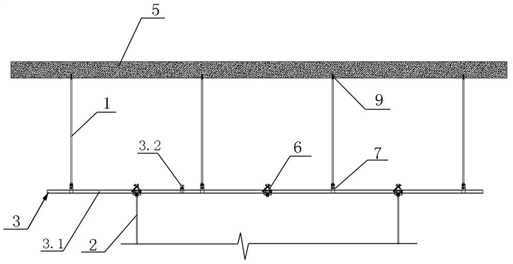
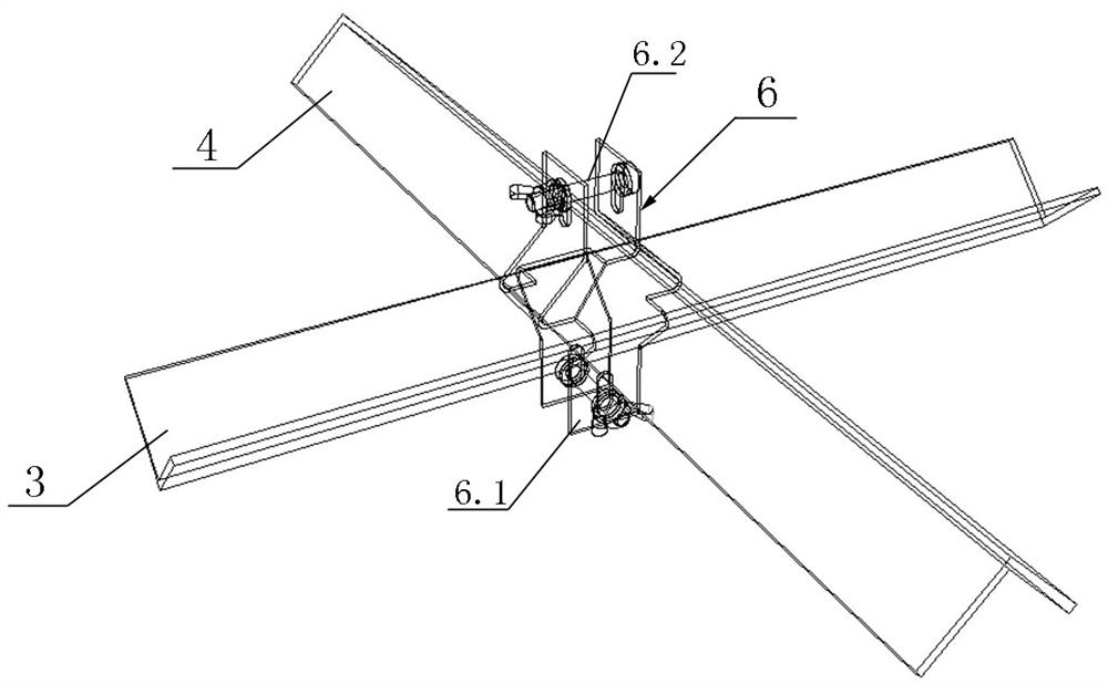
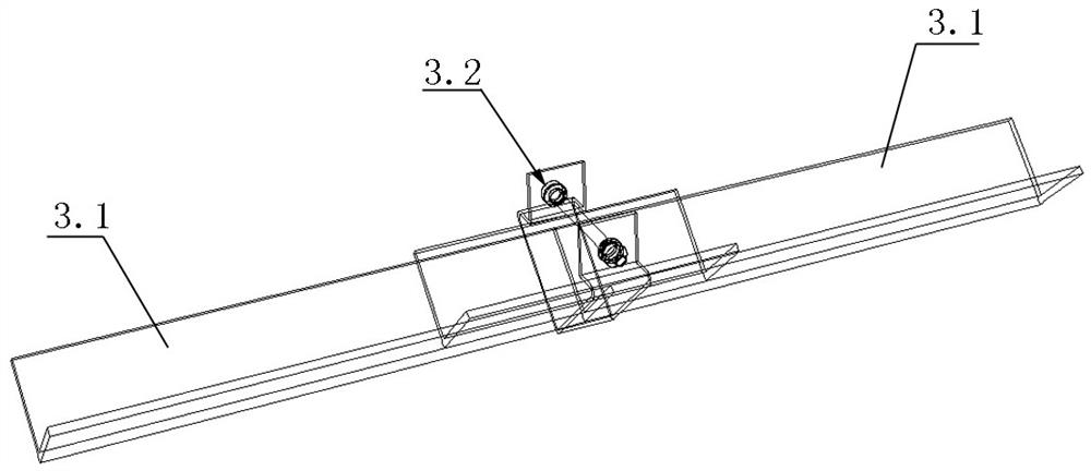
[0043] Such as Figure 1-12 As shown, this fast-installation transfer layer hanger bracket structure includes an upper boom 1, a lower boom 2, a transverse keel 3 and a longitudinal keel 4; the transverse keels 3 have a group and are arranged at intervals along the longitudinal direction; the longitudinal keels There is one group of 4, which are arranged at intervals along the transverse direction on the top of a group of transverse keels 3, and a group of longitudinal keels 4 and a group of transverse keels 3 jointly form the keel skeleton; the upper boom 1 is arranged with a set of , used to hang the keel frame below the floor 5; the lower boom 2 has a group, and a group is arranged on each longitudinal keel 4, which is used to hang the ceiling board under the keel frame; the transverse keel 3 and the longitudinal keel 4 are made of angle steel, and the notch of the transverse keel 3 faces upward, and the notch of the longitudinal keel 4 faces downward; the transverse keel 3...


PUM


Abstract

The invention discloses a quickly-mounted transfer layer crane support structure and a construction method thereof. The quickly-mounted transfer layer crane support structure comprises an upper hanging rod, a lower hanging rod, a transverse keel and a longitudinal keel, the keel framework is hung below a floor by the upper hanging rod; the ceiling plate is hung below the keel framework by the lower hanging rod; the transverse keels and the longitudinal keels are made of angle steel, notches of the transverse keels face upwards, and notches of the longitudinal keels face downwards; the transverse keels and the longitudinal keels are connected through keel stabilizing assemblies; the upper hanging rod is connected with the transverse keel through a first keel hanging piece; the lower hanging rod is connected with the longitudinal keel through a second keel hanging piece; the keel stabilizing assembly comprises a keel connecting piece and a first tie bolt; the first keel hanging piece comprises a first hanging plate, a first clamping plate and a first connecting bolt; the second keel hanging piece comprises a second hanging plate, a second clamping plate and a second connecting bolt. The technical problems that a traditional conversion layer structure is low in construction safety, threats physical health of constructors, is not beneficial to reduction of temporary electricity use and is high in indirect cost are solved.

Description

technical field [0001] The invention belongs to the technical field of decoration engineering, and in particular relates to a fast-installation conversion floor hanging bracket structure and a construction method thereof. Background technique [0002] The decoration project involves a large number of ceiling projects. The specification stipulates that when the length of the suspender is greater than 1.5m, counter supports should be set; when the suspender meets the equipment, the suspender should be adjusted and added; The transformation layer structure that needs to provide connections. The on-site ceiling conversion layer usually performs secondary processing on the profile and then welds it on site to realize its installation. The disadvantages are as follows: (1) The cutting and welding of the profile are hot construction, and the safety is low. (2 On-site welding and cutting will be The generation of a large amount of smoke and dust poses a threat to the health of cons...

Claims


Application Information

Patent Timeline
Patent Type & Authority Applications(China)
IPC IPC(8): E04B9/18E04B9/06E04B9/16
CPCE04B9/18E04B9/06E04B9/16E04B9/065
Inventor 刘凌峰周雨嫣朱融双晨晨车志岩刘永多
Owner CHINA STATE DECORATION GRP
Learn More