Engineering illuminating lamp with remote monitoring system

A remote monitoring system and lighting technology, applied in lighting devices, lighting devices, with built-in batteries, etc., can solve the problem that engineering lighting cannot be remotely monitored, the service life of the lamp is greatly affected, and the engineering lighting is inconvenient to move, etc. problems, to achieve the effect of increasing practicability, increasing the scope of application, and improving the service life

Pending Publication Date: 2022-02-08
江苏宏洁智慧科技有限公司
View PDF0 Cites 0 Cited by
  • Summary
  • Abstract
  • Description
  • Claims
  • Application Information

AI Technical Summary

Problems solved by technology

[0003] The existing engineering lighting cannot be remotely monitored, and the cooling effect of the existing engineering lighting is poor, which has a great impact on the service life of the lamp tube, and the existing engineering lighting cannot be adjusted in height, and the use range is low. Moreover, the existing engineering lighting lamps are not convenient to move, and can only be used in a fixed position during use, so the practicability is low

Method used


Image

  • Engineering illuminating lamp with remote monitoring system
  • Engineering illuminating lamp with remote monitoring system
  • Engineering illuminating lamp with remote monitoring system

Examples


Embodiment 1

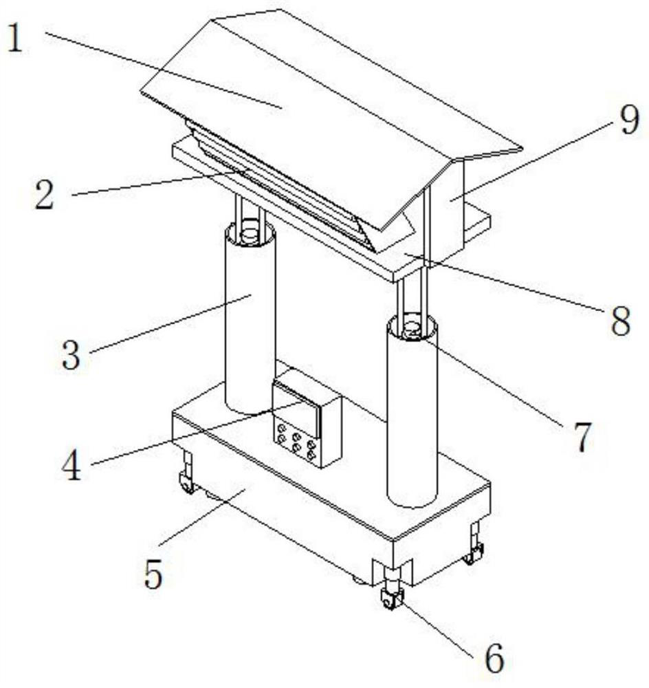
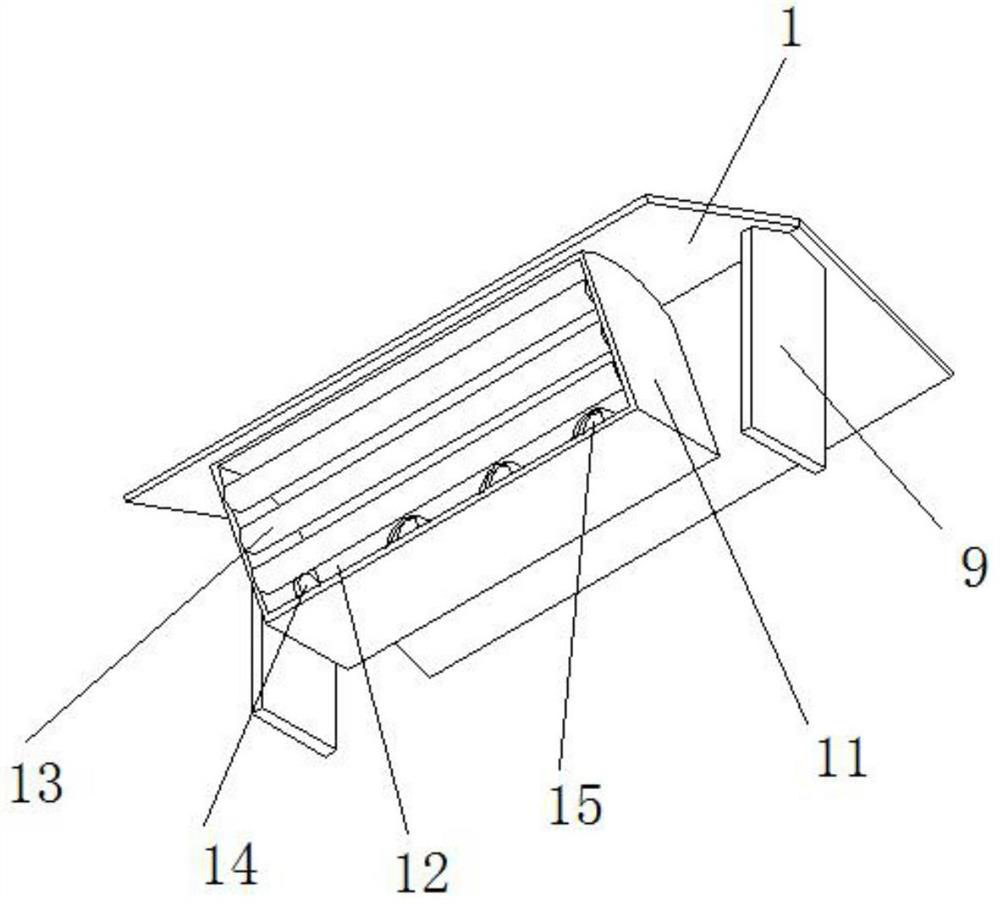
[0025] refer to Figure 1-4 As shown, an engineering lighting lamp with a remote monitoring system includes a lighting mechanism 2, a controller 4, a moving mechanism 6, an adjusting mechanism 7, and a cooling mechanism 15. The lighting mechanism 2 is composed of a mounting plate 8 and a mounting block 11. Block 11 is welded on the top of mounting plate 8, mounting block 11 side outer wall is provided with mounting groove 12, mounting groove 12 both sides inner walls are equipped with lighting tubes 13 equidistantly distributed, cooling mechanism 15 is composed of cooling fan 16, cooling box 17, The semiconductor refrigerating sheet 18 and the heat dissipation pipe 19 are formed, and the inner wall on one side of the installation groove 12 is provided with installation openings distributed equidistantly. The cooling fan 16 is installed on the inner wall of the installation opening. The side outer wall is provided with equidistantly distributed connecting ports, the semiconduct...

Embodiment 2

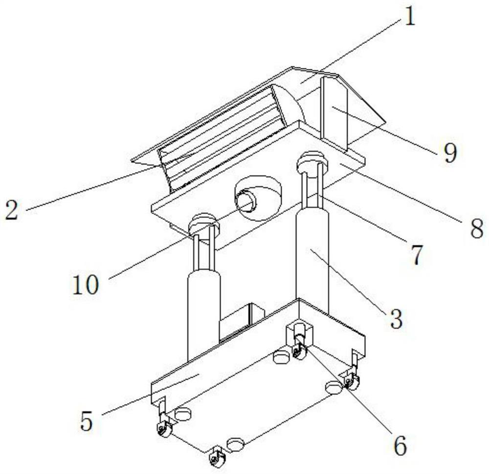
[0027] refer to Figure 5-6 As shown, the adjustment mechanism 7 is composed of a counterweight 5, a bearing 21, a threaded rod 24, a low-speed motor 25 and a fixing ring 28. Both ends of the top of the counterweight 5 are provided with fixing grooves 27, and the low-speed motor 25 is welded to the fixing groove 27. The inner wall of the bottom, the threaded rod 24 is connected to the output end of the low-speed motor 25, the fixing ring 28 is screwed to the outer wall of the threaded rod 24, the two ends of the top of the fixing ring 28 are welded with guide rods 23, the top of the guide rod 23 is welded with a top plate 22, and the bearing 21 It is welded to the top of the top plate 22, and the top of the bearing 21 is welded to the bottom of the mounting plate 8. A cover plate 26 is installed on the top of the counterweight 5, and two guide tubes 3 are welded on the top of the cover plate 26. The guide tube 3 and the outer wall of the fixed ring 28 form Slip fit.

Embodiment 3

[0029] refer to Figure 7 As shown, the moving mechanism 6 is composed of an electric push rod 30 and a universal wheel 21. The four corners of the bottom of the counterweight 5 are provided with connecting grooves 29, the electric push rod 30 is welded to the inner wall of the top of the connecting groove 29, and the universal wheel 21 is welded to the electric The bottom of the push rod 30, the four corners of the bottom of the counterweight 5 are bonded with rubber contact blocks 32, the outer walls of both sides of the mounting plate 8 are welded with a vertical plate 9, and the top of the vertical plate 9 is welded with a rain shelter 1, the lighting mechanism 2, the mobile The mechanism 6, the regulating mechanism 7, the monitor 10 and the cooling mechanism 15 are all connected to the output end of the controller 4 through wires, and the controller 4 is connected to the power line.

[0030] Through the operation of the low-speed motor 25 arranged inside the fixing groove...


PUM


Abstract

The invention discloses an engineering illuminating lamp with a remote monitoring system. The engineering illuminating lamp comprises an illuminating mechanism, a controller, a moving mechanism, an adjusting mechanism and a cooling mechanism, wherein the illuminatingmechanism comprises a mounting plate, a mounting block welded to the top of the mounting plate, a mounting groove formed in the outer wall of one side of the mounting block and illuminating lamp tubes mounted on the inner walls of the two sides of the mounting groove and distributed at equal intervals, and the cooling mechanism comprises mounting ports formed in the inner wall of one side of the mounting groove and distributed at equal intervals, cooling fans mounted on the inner walls of the mounting ports, a cooling box welded to the outer wall of one side of the mounting block, and connecting ports formed in the outer wall of one side of the cooling box and distributed at equal intervals. According to the invention, a controller controls a semiconductor chilling plate to operate to cool air in a cooling box, and the cooled air can quickly cool illuminating lamp tubes through operation of cooling fans, so that the cooling speed of the device can be greatly increased, the service life of the device is greatly prolonged to a certain extent, the practicability of the device is improved, and the safety is improved.

Description

technical field [0001] The invention relates to the technical field of engineering lighting lamps, in particular to an engineering lighting lamp with a remote monitoring system. Background technique [0002] Lighting lamp is a lamp with lighting function. Lighting lamp can be divided into LED lighting, emergency lighting, semiconductor lighting, solar lighting, surgical lighting, mechanical lighting and engineering lighting, among which engineering lighting is in It is widely used in engineering construction and engineering maintenance. [0003] The existing engineering lighting cannot be remotely monitored, and the cooling effect of the existing engineering lighting is poor, which has a great impact on the service life of the lamp tube, and the existing engineering lighting cannot be adjusted in height, and the use range is low. Moreover, the existing engineering lighting lamps are inconvenient to move, and can only be used at a fixed position during use, so the practicabi...

Claims


Application Information

Patent Timeline
IPC IPC(8): F21L2/00F21V33/00F21V29/54F21V29/60F21V29/67F21V29/61F21V21/14F21V21/15F21V21/36F21V21/06
CPCF21L2/00F21V33/00F21V29/54F21V29/60F21V29/67F21V29/61F21V21/14F21V21/15F21V21/36F21V21/06
Inventor 张红范恒远雷继张金鸣希
Owner 江苏宏洁智慧科技有限公司
Why Eureka
Try Eureka