Distance testing device for measuring temperature accuracy of infrared forehead thermometer

An accuracy and forehead temperature technology, applied in the field of infrared temperature measurement, can solve problems such as low efficiency, and achieve the effects of improving efficiency, avoiding scratches, and high measurement accuracy

Pending Publication Date: 2022-02-11
四川省药品检验研究院(四川省医疗器械检测中心)
View PDF0 Cites 0 Cited by
  • Summary
  • Abstract
  • Description
  • Claims
  • Application Information

AI Technical Summary

Problems solved by technology

[0004] The purpose of the present invention is to provide a test distance device for measuring the temperature accuracy of infrared forehead thermometers, which solves th

Method used


Image

  • Distance testing device for measuring temperature accuracy of infrared forehead thermometer
  • Distance testing device for measuring temperature accuracy of infrared forehead thermometer
  • Distance testing device for measuring temperature accuracy of infrared forehead thermometer

Examples


Embodiment 1

[0029] In order to solve the problems of the technologies described above, the present invention adopts the following solutions:

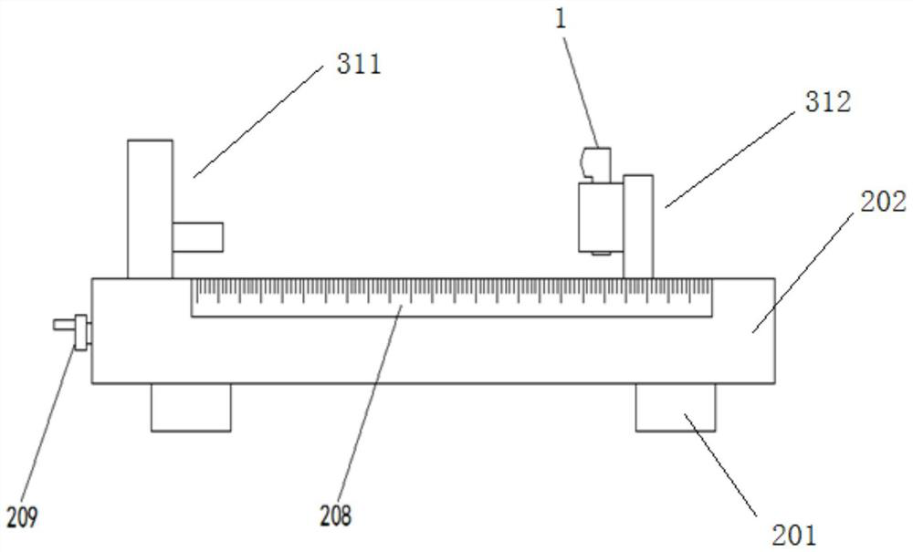
[0030] Such as figure 1 As shown, a test distance device for measuring the temperature accuracy of an infrared forehead thermometer 1 includes an infrared forehead thermometer 1, a base 202, an object stage 311 on the base 202, and a clamping structure 312. The table 311 is arranged opposite to the clamping structure 312, the clamping structure 312 is used to clamp the infrared forehead thermometer 1 and is slidably connected with the base 202, the test object is placed on the stage 311, and the base 202 is provided with a clamp for adjusting An adjustment mechanism for the distance between the holding structure 312 and the stage 311, and a scale 208 is provided on the side of the base 202.

[0031] In this embodiment, a base 201 is provided on the four corners of the bottom surface of the base 202, and the base 201 is used to raise the distance b...

Embodiment 2

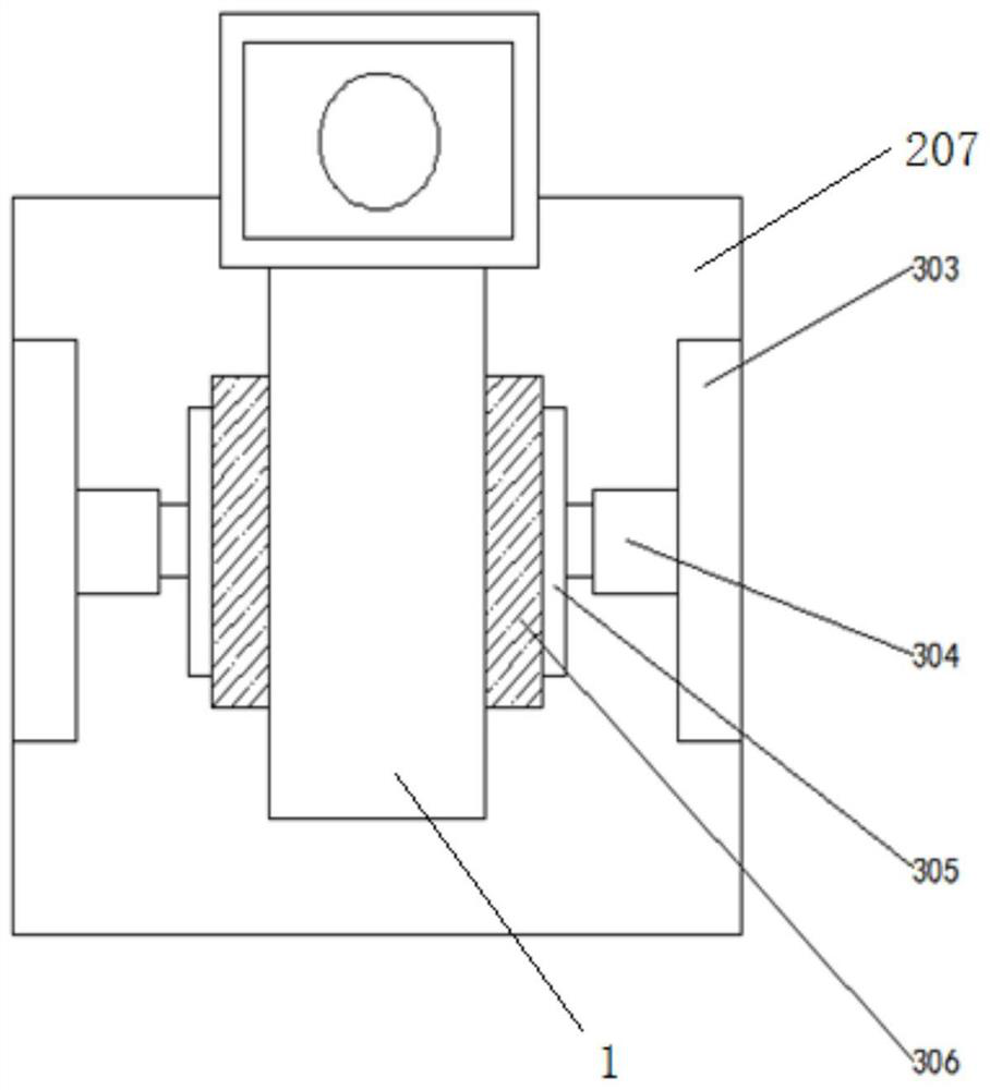
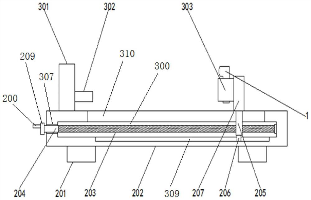
[0033] Such as figure 1 and 3 As shown, on the basis of the above-mentioned embodiments, the adjustment mechanism includes: a moving rod 205 that drives the clamping structure 312 to move, a driving member that drives the moving rod 205 to move, and the driving member is installed in the installation groove 300 inside the base 202 A sliding hole 310 on the base 202 is provided above the mounting groove 300 , and the top end of the moving rod 205 passes through the sliding hole 310 and is connected to the clamping structure 312 .

[0034] Preferably, the driving part is a threaded rod 203 , the two ends of the threaded rod 203 are respectively mounted on two opposite side walls of the groove 300 for rotational connection, and the threaded rod 203 runs through the moving rod 205 and is threadedly connected with the moving rod 205 .

[0035] Preferably, a bearing is fixedly connected to the right side wall of the installation groove 300, and the right end of the threaded rod 203...

Embodiment 3

[0039] Such as Figure 4 As shown, on the basis of Embodiment 1, the driving member is a hydraulic cylinder 308, the hydraulic cylinder 308 is fixed on the side wall of the base 202, and the output shaft 313 of the hydraulic cylinder 308 extends through the base 202 to the installation groove 300 and The mobile rod 205 is connected.

[0040]In this embodiment, the driving part is selected as a hydraulic cylinder 308, and the output shaft 313 of the hydraulic cylinder 308 drives the moving rod 205 to move left and right, thereby driving the clamping structure 312 and the infrared forehead thermometer 1 to move left and right, according to the front of the base 202 With the scale 208 on the back, the temperature measured by the infrared forehead thermometer 1 at different distances is compared, so as to achieve the purpose of measuring temperature accuracy of the infrared forehead thermometer 1 at different test distances.


PUM


Abstract

The invention discloses a distance testing device for measuring the temperature accuracy of an infrared forehead thermometer, which comprises an infrared forehead thermometer, a base, an objective table and a clamping structure, the objective table and the clamping structure are positioned on the base, the objective table is arranged opposite to the clamping structure, the clamping structure is used for clamping the infrared forehead thermometer and is in sliding connection with the base, a test object is placed on the objective table, an adjusting mechanism used for adjusting the distance between the clamping structure and the objective table is arranged in the base, and a graduated scale is arranged on the side face of the base. According to the invention, the problem of low efficiency of measurement at different positions due to the fact that the infrared forehead thermometer is manually held by hands in the prior art for measuring the accuracy distance of the infrared forehead thermometer is solved.

Description

technical field [0001] The invention relates to the technical field of infrared temperature measurement, in particular to a test distance device for measuring the temperature accuracy of an infrared forehead thermometer. Background technique [0002] The infrared thermometer uses the principle of radiation to measure the body temperature of the human body. It uses infrared sensors to sense the infrared rays radiated by the human body to measure the body temperature of the human body. Among them, the infrared forehead thermometer displays the body temperature of the measured object by measuring the thermal radiation of the forehead. At present, registration inspection and sampling inspection are required for the produced infrared forehead thermometers. The accuracy test distance of the existing infrared forehead thermometers is usually measured by manual hand-held infrared forehead thermometers at different positions. This measurement method is efficient Low, and the measurem...

Claims


Application Information

Patent Timeline
IPC IPC(8): G01J5/90G01J5/02G01J5/07
CPCG01J5/0205G01J5/0275
Inventor 石盛东瞿倩赖玉菡李娟孙波魏慧超
Owner 四川省药品检验研究院(四川省医疗器械检测中心)
Why Eureka
Try Eureka