
A rock test sample cutting device and cutting method in a fidelity environment

A rock test and cutting device technology, applied in the preparation of test samples, measuring devices, sampling, etc., can solve the problems of low processing efficiency, less available quantity, and core distortion, so as to reduce the scrap rate and avoid pollution damage Effect

Active Publication Date: 2022-06-17
CHINA UNIV OF MINING & TECH
View PDF0 Cites 0 Cited by
  • Summary
  • Abstract
  • Description
  • Claims
  • Application Information

AI Technical Summary

Problems solved by technology

[0004] Rock test samples are processed from rock cores, which need to be cut and processed into required shapes such as hexagons and cylinders according to the test requirements, and the rock cores are mined from deep areas, where the environment has high pressure and high pressure. The characteristics of temperature, conventional drilling and processing will cause the release of stress and temperature, which will make the core "distorted". The high cost of collecting deep cores with little availability is a problem that plagues the academic and industrial circles

Method used


Image

  • A rock test sample cutting device and cutting method in a fidelity environment
  • A rock test sample cutting device and cutting method in a fidelity environment
  • A rock test sample cutting device and cutting method in a fidelity environment

Examples


Embodiment 1

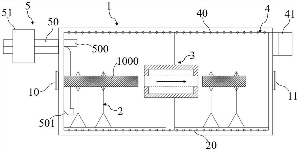
[0060] The rock test sample cutting device under the fidelity environment of this embodiment includes:

[0061] The fidelity cabin 1 is a closed structure, and the left and right ends are respectively provided with a feeding port 10 and a discharging port 11;

[0062] The displacement unit 2 is arranged in the fidelity cabin 1 and transports the core 1000 in the fidelity cabin 1;

[0063] The cutting unit 3, which is arranged in the fidelity cabin 1, cuts the core 1000;

[0064] The temperature control unit 4, which is connected to the fidelity cabin 1, controls the temperature in the fidelity cabin 1;

[0065] The pressurizing unit 5, which is connected to the fidelity cabin 1, controls the pressure in the fidelity cabin 1.

[0066] like figure 1 As shown in the figure, the fidelity chamber 1 of this embodiment is in the shape of a hollow cylinder, and a feeding port 10 and a discharging port 11 are respectively formed on both ends of the fidelity chamber 1, which are respec...

Embodiment 2

[0070] The rock test sample cutting device in the fidelity environment of this embodiment is further improved on the basis of Embodiment 1, and the displacement unit 2 includes:

[0071] The track 20 is laid on the bottom of the fidelity capsule 1 along the length direction of the fidelity capsule 1;

[0072] One end of the manipulator is slidably connected to the track 20, and the other end holds the core 1000.

[0073] like figure 1 As shown, in this embodiment, there are three manipulators, one manipulator, No. 2 manipulator and No. 3 manipulator from left to right, wherein the No. 1 manipulator and No. 2 manipulator are located on the left side of the cutting unit 3, close to the feeding Port 10, the No. 1 manipulator and No. 2 manipulator are separated by 30cm, which are used to hold and move the core 1000 to be cut. The No. 3 manipulator is located on the right side of the cutting unit 3, close to the discharge port 11, used for holding and transporting after cutting r...

Embodiment 3

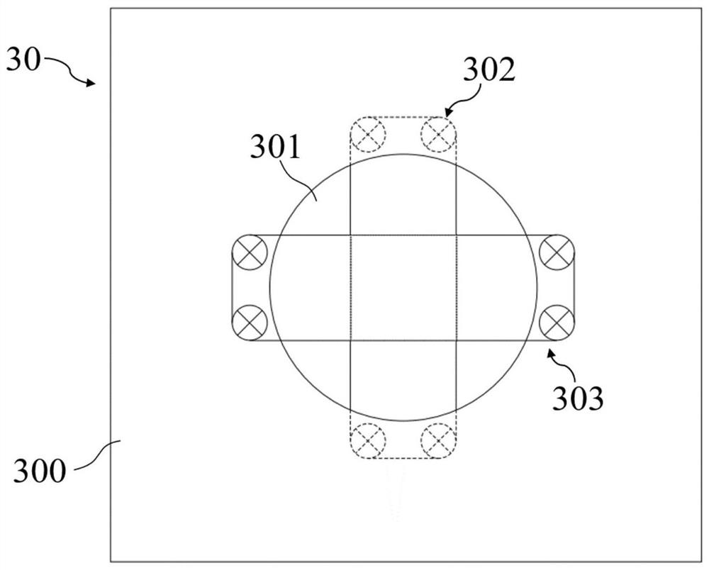
[0075] The rock test sample cutting device in the fidelity environment of this embodiment is further improved on the basis of Embodiment 2. The cutting unit 3 includes a square cutting part 30, which includes:

[0076] Mounting seat one 300, which is movably connected with the inner wall of the fidelity cabin 1;

[0077] A sample port one 301, which runs through the mounting seat one 300, for the core 1000 to pass through;

[0078] The longitudinal cutting member 302 includes four driving wheels and an emery wire, the driving wheels are distributed on the upper and lower sides of the sample port one 301 in two, and the emery wire surrounds each driving wheel to form a longitudinal rectangle in the longitudinal direction;

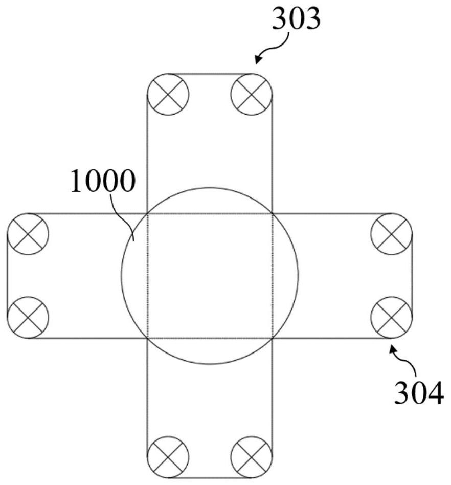
[0079] The transverse cutting member 303 also includes four driving wheels and a diamond wire. The driving wheels are distributed on the left and right sides of the sample port 1 301. The diamond wire surrounds each driving wheel to form a rectangle whose le...


PUM


Abstract

The invention discloses a rock test sample cutting device and a cutting method in a fidelity environment, and belongs to the technical field of rock sample preparation. The device includes a fidelity cabin; a displacement unit, which transports the rock core in the fidelity cabin; a cutting unit, which cuts the rock core; a temperature control unit, which controls the temperature in the fidelity cabin; The pressure in the real cabin. The rock test sample cutting device in a fidelity environment of the present invention does not need to manually adjust the position of the rock core, avoids the rock core from being polluted and damaged, and ensures that the rock core is always in the original position under the stress of buried depth and ground temperature. The sample positioning is completed by the external control system of the fidelity cabin, which cooperates with the temperature control unit and the pressurization unit, so that the core to be cut is always kept in the deep in-situ high-temperature and high-pressure environment for cutting and preparation, and the original position of the deep rock is kept to the greatest extent. Features, improve sample preparation efficiency and sample quality, and provide necessary in-situ cores for obtaining in-situ rock mechanical parameters.

Description

technical field [0001] The invention belongs to the technical field of rock sample preparation, and more particularly relates to a cutting device and a cutting method for rock test samples in a fidelity environment. Background technique [0002] With the decrease of shallow resources, deep mining has become an inevitable trend of mineral resources mining at home and abroad. The rock mechanics problems generated in deep mining engineering are the focus of research in mining and rock mechanics at home and abroad. Existing rock mechanics The rock samples for the mechanical test are all obtained by deep drilling, releasing the in-situ stress and in-situ temperature, and then processing them. Therefore, the rock samples no longer have the characteristics of in-situ rock mechanics, and the test results cannot reflect the original mechanical properties of rock. [0003] Therefore, the preparation of rock test samples in a fidelity environment is the primary key issue in the study ...

Claims


Application Information

Patent Timeline
Patent Type & Authority Patents(China)
IPC IPC(8): G01N1/28B28D1/32B28D7/00B28D7/02
CPCG01N1/286B28D1/327B28D7/005B28D7/02G01N2001/2873
Inventor 高亚楠兰东昊王云龙张玉栋郭鹏丁峰高峰
Owner CHINA UNIV OF MINING & TECH
Learn More