Design method for progressive collapse resistance of structure and ultimate bearing capacity calculation method

A technology of ultimate bearing capacity and calculation method, applied in truss-type structures, special data processing applications, instruments, etc., can solve the problems that the structure cannot meet the multi-hazard design and fortification requirements, increase the cost, and be difficult to construct, and improve the continuous resistance of the structure. Collapse performance, conflict mitigation, adaptive effects

Pending Publication Date: 2022-02-11
TONGJI UNIV
View PDF0 Cites 2 Cited by
  • Summary
  • Abstract
  • Description
  • Claims
  • Application Information

AI Technical Summary

Problems solved by technology

It is worth noting that for structures with seismic fortification requirements, directly increasing the reinforcement ratio of the longitudinal reinforcement in the beam will lead to the unfavorable failure mode of "strong beam like column" under the earthquake, which will lead to the failure of the structure. Meet the f

Method used


Image

  • Design method for progressive collapse resistance of structure and ultimate bearing capacity calculation method
  • Design method for progressive collapse resistance of structure and ultimate bearing capacity calculation method
  • Design method for progressive collapse resistance of structure and ultimate bearing capacity calculation method

Examples


Embodiment 1

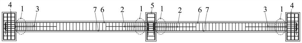
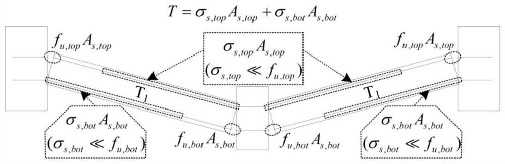
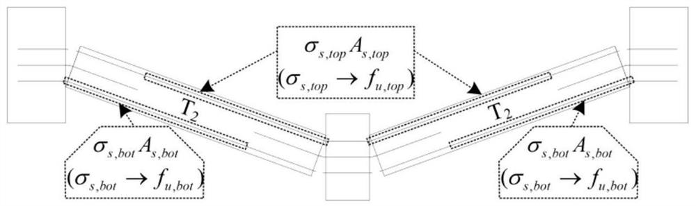
[0063] Figure 4 In order to design a sub-structure designed in conventional methods and a continuous collapse resistance to a sub-structure designed by the invention. The design technique proposed in the present invention is a longitudinal short steel bib 2 in which a half-high positional addition and concrete partially delayed longitudinal short steel bib 2 is partially delayed in the near-side reinforcement, and the concrete is bonded to the concrete. accomplish. As shown in FIG. 2 (a), a sub-structure designed according to conventional methods, at the top longitudinal rib 5 and the near-middle column 6 bottom longitudinal ribs 7 due to the change concentration, the near-edge column 4 is broken due to the change of the concentrated phenomenon. The presence of beam end 1 bottom longitudinal ribs 7 and the near-middle column 6 longitudinal rib 5 can continue to provide resistance, but the power can be provided, which is mainly due to two reasons: 1 Beam 5,7 tensile properties hav...


PUM


Abstract

According to the method capable of improving the progressive collapse resistance of the structure, the limit rotation capacity of a beam end is improved, so that the tensile property of a longitudinal bar outside a strain concentration area is fully utilized, and the effect of a catenary is more completely exerted. Longitudinal short steel bars partially debonded with concrete are additionally arranged in a near-beam end area, and the short steel bars are arranged at the half-height position of a beam section, so that resistance continues to be provided after longitudinal bars at the top of a near-side column beam end or longitudinal bars at the bottom of a near-middle column beam end are broken, and continuous collapse of the structure is prevented. Local debonding of the longitudinal short steel bars and the concrete is achieved by wrapping the surfaces of the short steel bars with thermal polycondensation olefin pipes. The invention further provides an ultimate bearing capacity calculation method of the beam-column structure additionally provided with the short steel bars at the half-height position of the beam section. The progressive collapse resistance design technology provided by the invention has the advantages that the practice is easy, the anti-seismic property of the structure is not obviously influenced, and the economical efficiency is good; and the given ultimate bearing capacity analysis model has the characteristics of simplicity and accuracy.

Description

Technical field [0001] The present invention belongs to the field of civil engineering technology, and the design technology of anti-structural continuous collapse is related to the design technology of continuous collapse and the analysis model of continuous collapse ultra-limit load. Background technique [0002] Building structures are likely to suffer multi-disasters during its service period, such as earthquake effects, explosions and impacts, etc., which brings huge challenges to the design structure. For reinforced concrete (RC) frame structures in one of the most common structural systems, the collapse of the collapse and the occasional effect caused by the seismic effect is the most prone to the two disasters, and often brings huge casualties and Economic losses. The construction structure is partially destroyed due to accidental effects. For continuous collapse damage, the GSA and DOD specification recommends using an alternative load path (AP) method for structural res...

Claims


Application Information

Patent Timeline
IPC IPC(8): G06F30/13E04C3/20G06F119/14
CPCG06F30/13E04C3/20G06F2119/14
Inventor 杨兴据徐哲林峰顾祥林
Owner TONGJI UNIV
Why Eureka
Try Eureka