Automatic driving lane information detection method based on radar point cloud and image fusion
An image fusion and automatic driving technology, which is applied in the directions of measuring devices, surveying and mapping and navigation, road network navigators, etc., can solve the problem of discontinuous radar point cloud, easy to cause false detection and missed detection, and it is difficult to meet the needs of unmanned driving tasks and other issues to achieve a good effect of robustness and detection success rate
- Summary
- Abstract
- Description
- Claims
- Application Information
AI Technical Summary
Problems solved by technology
Method used
Image

Examples
Embodiment Construction
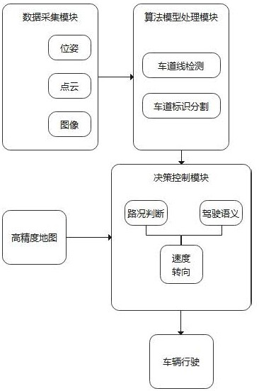
[0019] To make the above-mentioned purposes, features and advantages of the present invention more obvious and understandable, below in conjunction with the attached Figure 1 ~ Figure 4 The present invention will be further described in detail with specific embodiments.
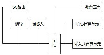
[0020] In this embodiment, a detection method for automatic driving lane information based on radar point cloud and image fusion is adopted, such as figure 1 The system architecture shown is implemented and passed through figure 2 The data lines shown are connected. The system includes a sensor group composed of lidar, camera and inertial navigation to collect and process data, a core computing unit and an embedded computing unit for data calculation, 5G routing, between sensors in the sensor group, and between sensor groups and core computing Units and embedded computing units are connected through HUB. In this implementation, the embedded computing unit is used to preprocess the data. The core computi...
PUM
 Abstract
Description
Claims
Application Information
PatSnap Eureka turns technology decisions into work you can execute. Powered by our Innovation Knowledge Graph, it runs expert workflows across engineering, life sciences, materials and intellectual property. Get your review-ready output in minutes.


