Reducing clamp for damping bushing

A diameter reducing and clamping technology, which is applied in the field of reducing clamps for shock absorbing bushes, can solve the problems of large or small size, low pass rate, poor appearance quality, etc., and achieve the effect of avoiding small size and increasing pressure

Pending Publication Date: 2022-02-15
ANHUI ZHONGDING NVH
View PDF0 Cites 0 Cited by
  • Summary
  • Abstract
  • Description
  • Claims
  • Application Information

AI Technical Summary

Problems solved by technology

[0003] There are a lot of tooling to achieve diameter reduction, but the diameter reduction size cannot be well controlled, and it is easy to cause the size to be too large or too small. In addition, the surface is prone to unevenness, burrs, indentations, etc., resulting in poor appearance quality and low pass rate.

Method used


Image

  • Reducing clamp for damping bushing
  • Reducing clamp for damping bushing
  • Reducing clamp for damping bushing

Examples


Embodiment 1

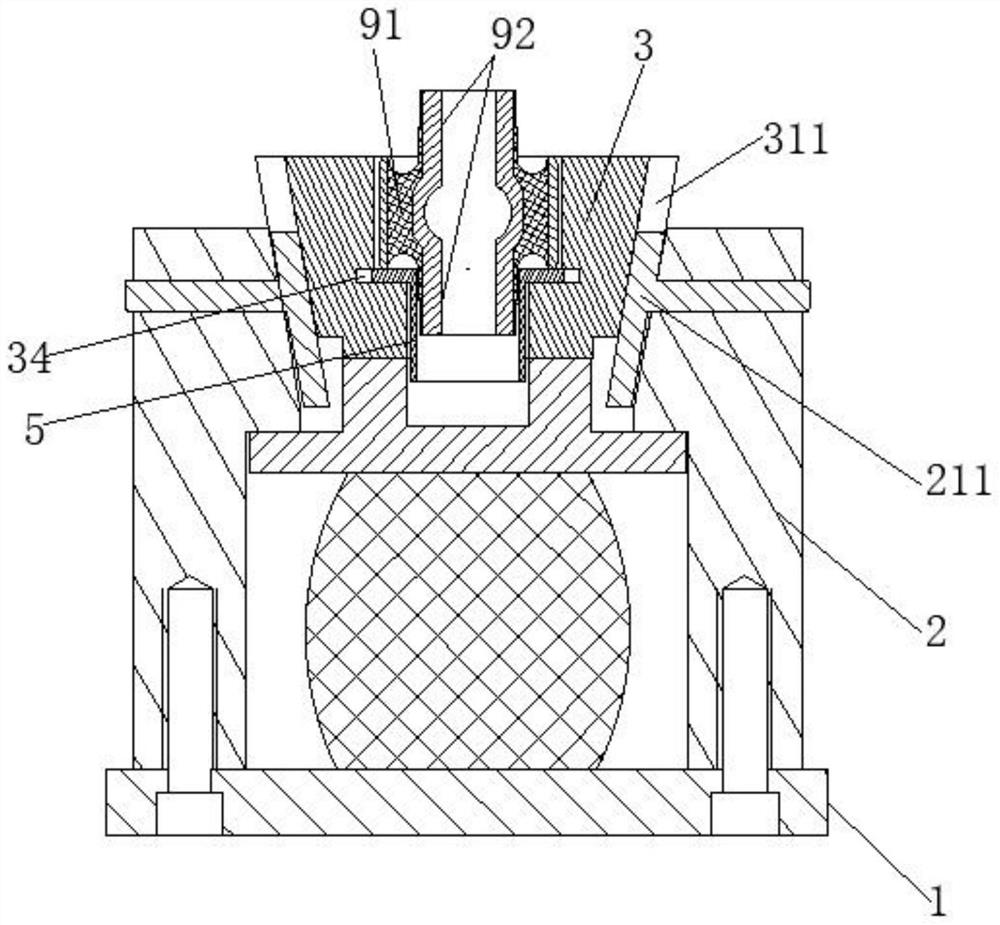
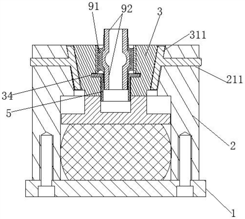
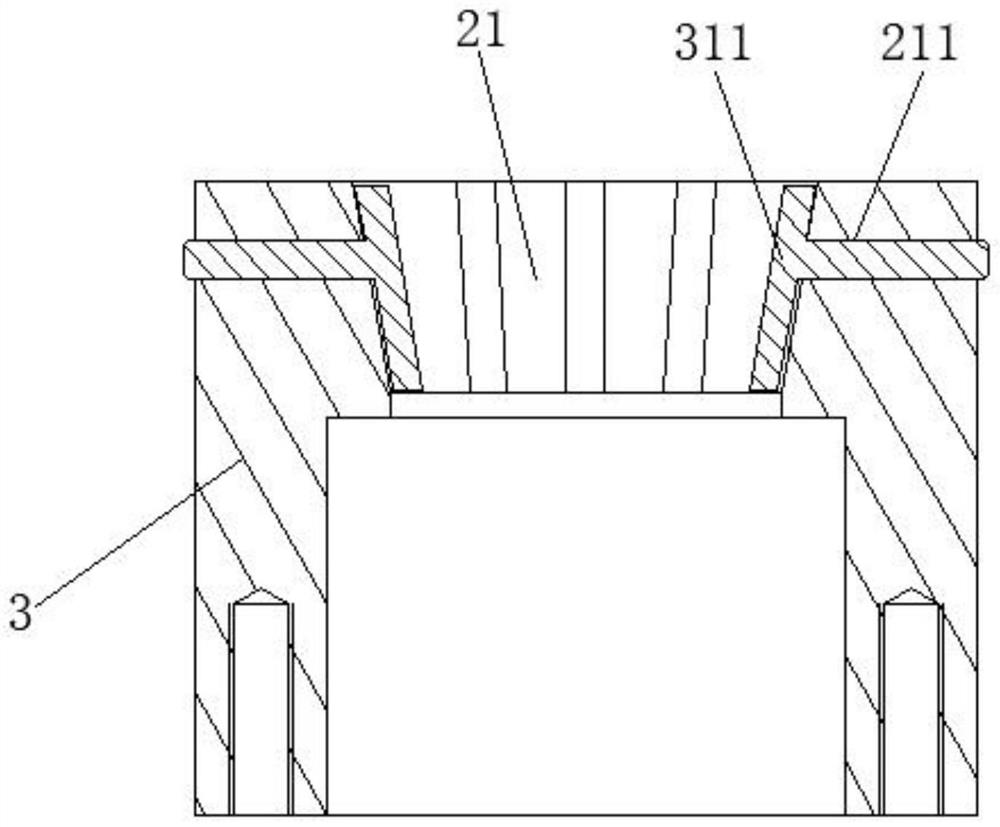
[0029] like Figure 1 - Figure 7 As shown in this embodiment, the damping bush jig with a reduced diameter, for the liner is reduced in diameter, the liner comprising a reduced diameter section 91 and the non-reduced diameter section 92, the reduced diameter section 92 is located non-condensing diameter section 91 at both ends, comprises a base 1, a clamp 2, 3 and a plurality of Hough ram; the clamp 2 is fixed to the base 1, the clamp 2 is arranged in a cylindrical shape, arranged for placement intermediate Hough 3 of shrinkage holes 21, shrinkage of the inclined inner wall provided with a hole 21, and the diameter is gradually reduced from top down; Huff inclined outer wall portion 21 of the inner wall 3 is provided with a shrink fit hole 31, the Hough the inner wall 3 is arranged sequentially from top to bottom reduced-diameter portion 32 and a stopper portion 33; a plurality of annular arrays Hough 3 distributed within the shrinkage holes 21, a plurality of the inclined portion ...

Embodiment 2

[0037] like Figure 7 , Figure 8As shown, the present embodiment is replaced with the restricted ring 51 of the outer wall of the limit element 5 to the limit column 52 compared to the first embodiment, and the limit slot 34 used in combination with the limit ring 51 is replaced with the limit column. 52 mating column slot 35.

[0038] By setting the finite casing 52 in the outer wall of the limit member 5, the limit seat member 5 is a ring array distribution; a column groove 35 that cooperates with the limit column 52 by the inner wall of the Haf 3; in the diameter, columnar The groove 35 slides along the limit position 52, and several Haf 3 maintain the same lower speed in the vertical direction, so that the diazilizing speed of several Haf 3 is always equal, and the minimum number of column 52 is performed on the tangent Limited, the Kaf 3 is only axially displaced along the limit column 52.

[0039] The limit post 52 is inclined in the horizontal direction; the horizontal heigh...


PUM


Abstract

The invention provides a reducing clamp for a damping bushing. The reducing clamp comprises a base, a clamp, a plurality of Halves and a pressing head. The clamp is fixed on the base, the clamp is cylindrical, a shrinkage hole is formed in the middle, the inner wall of the shrinkage hole is obliquely arranged, and the diameter of the shrinkage hole is gradually reduced from top to bottom; an inclined part is arranged on the outer wall of the Half, and a diameter shrinkage part and a limiting part are arranged on the inner wall of the Half; the plurality of Halves are distributed in the shrinkage hole in an annular array manner, the inclined parts of the plurality of Haves form an inverted circular truncated cone shape, and the diameter shrinkage parts form a cylinder shape to clamp a diameter shrinkage section; the limiting parts form a cylindrical shape and are distributed in an annular array around a non diameter shrinkage section; the pressing head comprises a contact part and a stress part; the stress part is knocked to enable the contact part to extrude the Halves downwards, when the Halves move downwards, the inclined parts slide along the inner wall of the shrinkage hole, the plurality of Halves get close gradually, and the diameter shrinkage parts extrude and reduce the diameter of the diameter shrinkage section till the limiting parts makes contact with the outer wall of the non diameter shrinkage section.

Description

Technical field [0001] The present invention relates to automotive suspension bushing technology, and particularly relates to a reduced-diameter shock absorbing liner clamps. Background technique [0002] In the prior art, as part of the meet performance requirements of the vehicle, often with the inner and outer damping hub metal structure, (common material 20 # steel, aluminum), rubber filling formed of a hollow outer annular portion inner employed. Presence shrinkage after curing rubber bush, the metal bush type requires a reduced diameter damping hub, eliminating the stress of deformation of rubber, increasing the durability of the damping bush. [0003] To achieve reduced diameter tooling are numerous, but not well controlled size reduced in diameter, is likely to cause bigger or smaller, and additional surface irregularities easily formed burr, indentation, etc., resulting in poor appearance quality, pass rate. Inventive content [0004] The present invention addresses def...

Claims


Application Information

Patent Timeline
Patent Type & Authority Applications(China)
IPC IPC(8): B21D41/04B21D53/88
CPCB21D41/04B21D53/88
Inventor 何仕生仇贵宏
Owner ANHUI ZHONGDING NVH
Why Eureka
Try Eureka