
Mold Design Method and Mold

A design method and casting mold technology, applied in casting molding equipment, design optimization/simulation, casting molds, etc., can solve the problems of insufficient size, only consider casting shrinkage and thermal deformation, and cannot fully ensure the design accuracy of cavity shape, etc., to achieve Effect of preventing undersizing and improving accuracy

Active Publication Date: 2016-12-14
KOSCO COMPRESSOR CO LTD
View PDF9 Cites 0 Cited by
  • Summary
  • Abstract
  • Description
  • Claims
  • Application Information

AI Technical Summary

Problems solved by technology

However, it is assumed that in the casting process, the mold is thermally deformed from pouring to the start of solidification due to the high-temperature molten metal, and the shape of the cavity of the mold at the start of solidification changes due to the thermal deformation.
Therefore, only the shrinkage and thermal deformation of the casting are considered, which has the problem that the design accuracy of the cavity shape cannot be sufficiently ensured
In addition, since it is expected that the thermal deformation of the mold caused by the molten metal will shrink the cavity, the machining allowance of the finished casting after casting may be insufficient, and defective products with insufficient dimensions may occur.

Method used


Image

  • Mold Design Method and Mold
  • Mold Design Method and Mold
  • Mold Design Method and Mold

Examples


Embodiment

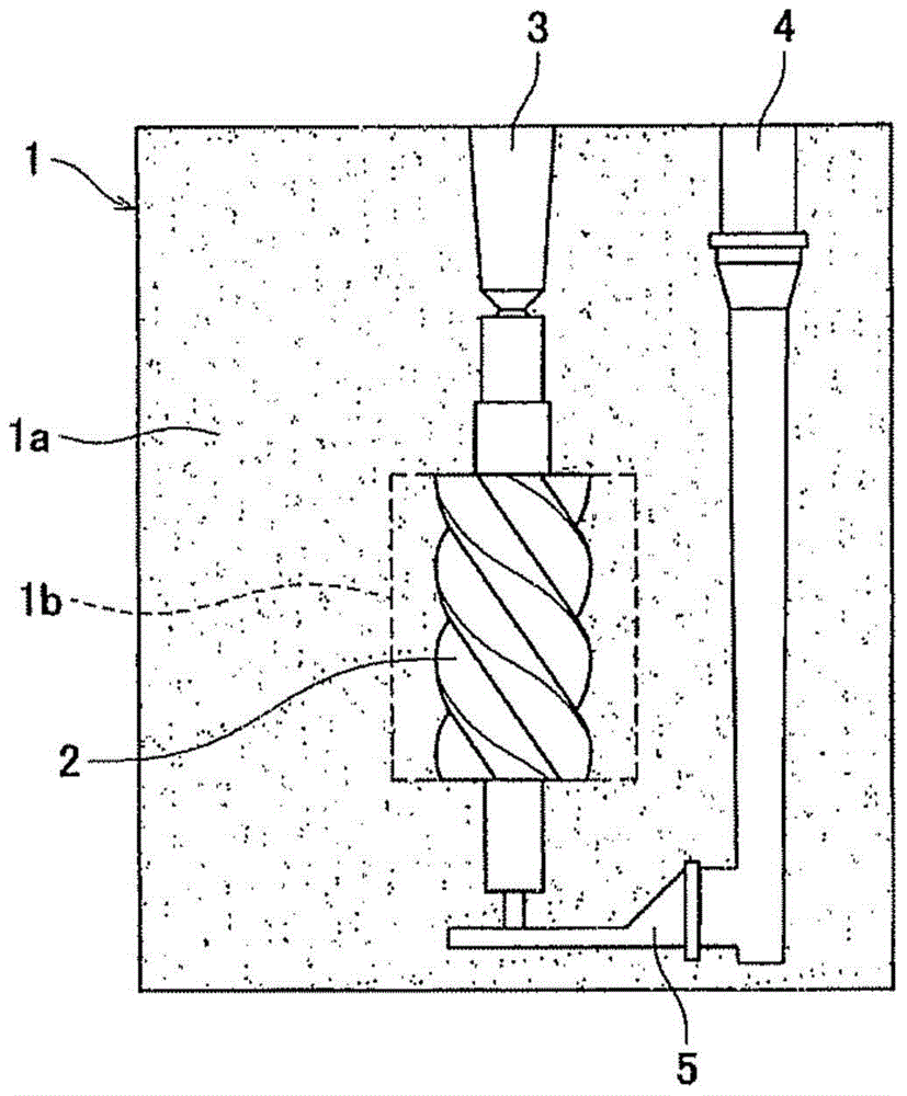
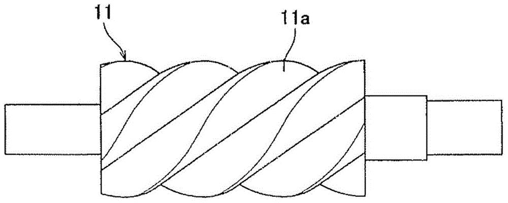
[0044] Figure 7 (a), (b) For the peak and valley of the screw part, the enlarged display is based on the Figure 6 The cavity cross-sectional shape of the embodiment of the casting mold is designed by adding the value of the deformation amount of the casting mold and the casting. Each figure also shows a cavity cross-sectional shape designed in consideration of the amount of deformation of the casting from the start of solidification to the end of cooling as a comparative example. In the comparative example in which the amount of deformation of the mold from pouring to the start of solidification was not considered, in Figure 7 The shrinkage amount of the valley portion of the screw portion shown in (b) is expected to be small, and the cavity diameter of the valley portion is designed to be smaller than that of the embodiment. Therefore, the machining allowance of 2 mm is cut off in the valley of the screw part, and the finished casting may become a defective product with ...


PUM

PropertyMeasurementUnit
sizeaaaaaaaaaa
sizeaaaaaaaaaa
sizeaaaaaaaaaa

Abstract

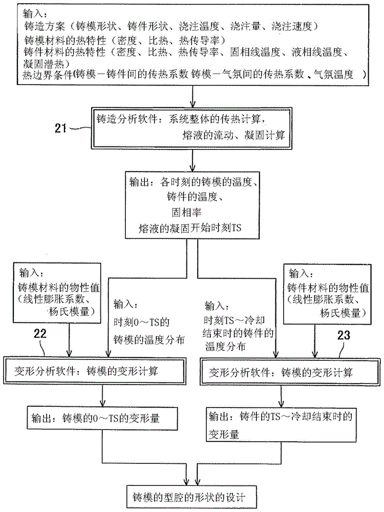
In the present invention, not only the deformation amount from the start of solidification of the casting to the end of cooling is obtained by the deformation analysis software (23), but also the deformation amount of the casting mold from pouring to the start of solidification is obtained by the deformation analysis software (22). . The shape of the cavity is designed based on the calculated deformation of the mold and the casting, thereby reflecting the cavity shape of the mold at the beginning of solidification on the design of the mold, thereby further improving the accuracy of the near-net shape, and preventing post-casting The finished castings are undersized.

Description

technical field [0001] The present invention relates to a casting mold design method and a casting mold for designing a cavity shape of a casting mold. Background technique [0002] Casting molds for castings generally use sand molds. When casting castings with complicated shapes, etc., the casting mold may consist of a main mold body and a mold core. Silica sand is often used as molding sand to form a sand mold, and a binder such as resin is usually kneaded in order to improve mold fabrication. [0003] In the casting industry, in order to reduce the machining allowance of the casting after casting, the so-called near net shape (near net shape) that makes the shape of the cast casting product close to the final product shape is promoted. In such near-net-shape casting, the cavity shape of the mold is designed in anticipation of the amount of thermal shrinkage of the casting called scale. For example, when the casting material is gray cast iron and spheroidal graphite cas...

Claims


Application Information

Patent Timeline
Patent Type & Authority Patents(China)
IPC IPC(8): B22C7/00
CPCB22C9/00B22C9/10B22C9/22B22C9/02G06F30/23
Inventor 堤一之片冈保人
Owner KOSCO COMPRESSOR CO LTD
Learn More