
Pre-assembly clamp for automobile welding production

A pre-assembly, automotive technology, applied in auxiliary devices, manufacturing tools, welding equipment, etc., can solve the problems of affecting parts welding, large parts errors, parts not in the same horizontal position, etc., to improve welding accuracy, reduce Adjust the difficulty and save the effect of manual adjustment process

Inactive Publication Date: 2022-02-15
XINXIANG VOCATIONAL & TECHN COLLEGE
View PDF0 Cites 0 Cited by
  • Summary
  • Abstract
  • Description
  • Claims
  • Application Information

AI Technical Summary

Problems solved by technology

[0004] In order to overcome the large error of the parts after welding, and when adjusting the position of the parts, the welding between the parts is affected, and it is easy to make one end of the parts higher and the other end lower, resulting in the parts after the welding are not in the same horizontal position. The invention provides A pre-assembled fixture for automobile welding production

Method used


Image

  • Pre-assembly clamp for automobile welding production
  • Pre-assembly clamp for automobile welding production
  • Pre-assembly clamp for automobile welding production

Examples


Embodiment 1

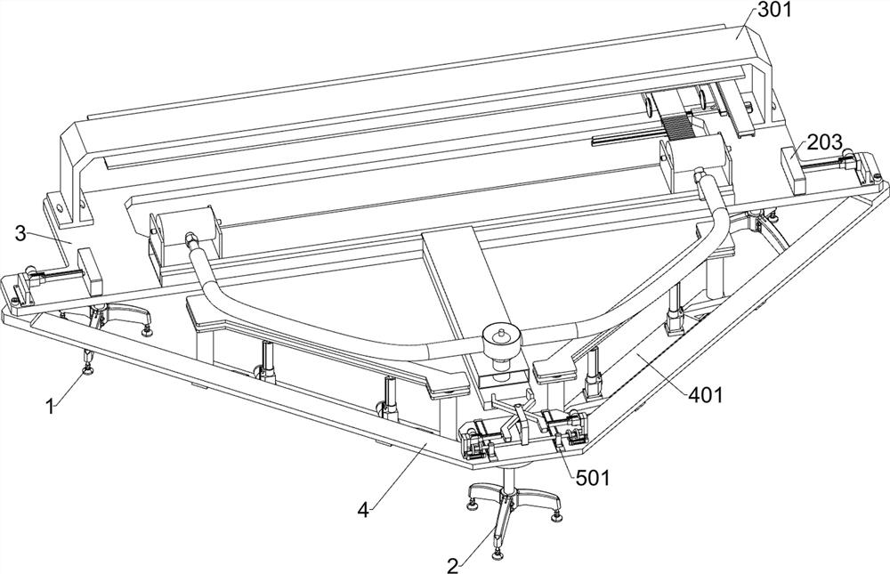
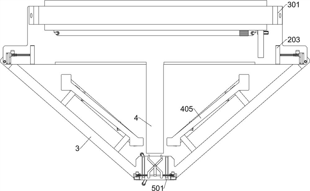
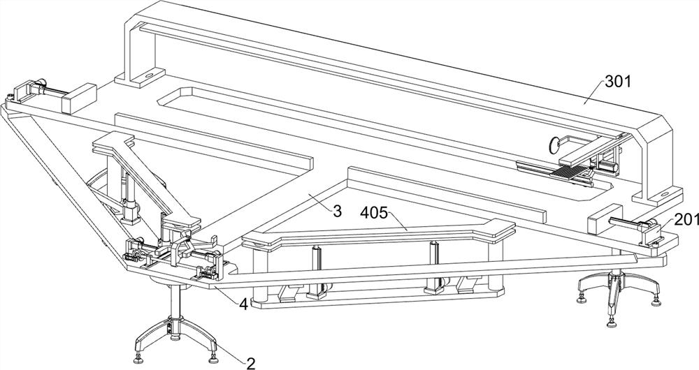
[0032] A pre-assembled fixture for automobile welding production, such as Figure 1-11 As shown, it includes a first foot 1, a second foot 2, a mounting plate 3, a V-shaped mounting plate 4, a positioning unit, an adjustment fixing unit and a height fixing unit; the first foot 1 is provided with two , the two first footings 1 are respectively located on the left and right sides of the lower surface of the mounting plate 3; the upper surface of the second footing 2 is welded with a V-shaped mounting plate 4; the front side of the mounting plate 3 is bolted to the V-shaped mounting plate 4; a positioning unit is installed on the front side of the upper surface of the installation and placement plate 3; an adjustment and fixing unit is installed on the rear side of the upper surface of the installation and placement plate 3; height-fixing units are installed on the left and right sides of the V-shaped installation plate 4.

[0033]The positioning unit includes a first connecting ...

Embodiment 2

[0044] On the basis of Example 1, such as figure 1 , Figure 12-13 As shown, a fine-tuning fixing unit is also included, and the middle part of the upper surface of the V-shaped mounting plate 4 is equipped with a fine-tuning fixing unit. 504, the fifth connecting plate 505, the seventh driving member 506, the clamping plate 507, the third connecting frame 508, the first connecting column 509, the second connecting column 5010, the fixed ring 5011, the fourth sliding rail 5012 and the eighth Drive member 5013; two symmetrical third slide rails 501 are installed in the middle of the upper surface of the V-shaped mounting plate 4; a sixth drive member 502 is slidingly connected within the two third slide rails 501; two sixth drive members 502 The upper side is penetrated and fixed with a second connecting rod 503; the outer surface of the second connecting rod 503 is equipped with two left and right symmetrical microrotators 504; the middle part of the outer surface of the seco...


PUM


Abstract

The invention relates to the field of automobiles, in particular to a pre-assembly clamp for automobile welding production. The technical problems to be solved are that: errors of welded parts are large, when the positions of the parts are adjusted, welding of the parts is affected, one ends of the parts are high, the other ends of the parts are low, and the welded parts are not located at the same horizontal position. According to the technical scheme, the pre-assembly clamp for automobile welding production comprises a mounting placement plate, a positioning unit and the like; and a positioning unit for positioning automobile supercharger parts is mounted on the front side of the upper surface of the mounting placement plate. According to the invention, before automobile supercharger parts are welded, the welded parts are positioned and fixed one by one, so that cold joint does not exist after all the parts are welded, the welding positions are standard, the two ends of each part are located at the same horizontal position, the manual adjusting process is omitted, the positions of all the parts are finely adjusted in a fine adjustment mode, and the welding precision is improved.

Description

technical field [0001] The invention relates to the field of automobiles, in particular to a pre-assembled fixture for automobile welding production. Background technique [0002] In the prior art, when welding the parts of the automobile supercharger, it is necessary to manually adjust the position of the parts, which leads to a large error of the parts after welding, and when the parts are adjusted, the welding between the parts is affected. ; [0003] Secondly, during welding, the height of the welded parts cannot be effectively judged. Manual adjustment can easily make one end of the part higher and the other end lower, resulting in the parts after welding being not at the same level and unable to be used in actual use. Contents of the invention [0004] In order to overcome the large error of the parts after welding, and when the position of the parts is adjusted, the welding between the parts is affected, and it is easy to make one end of the part high and the other...

Claims


Application Information

Patent Timeline
Patent Type & Authority Applications(China)
IPC IPC(8): B23K37/04
CPCB23K37/0443
Inventor 高恩娟王飞龙李艳张明程致梁
Owner XINXIANG VOCATIONAL & TECHN COLLEGE
Learn More