
Shutter structure for pen

A shutter and pen technology, applied to ink pens, printing, and writing utensils with ink storage tubes in the pen barrel, can solve problems such as large diameter requirements, achieve higher requirements, reduce complexity, and reduce installation costs.

Pending Publication Date: 2022-02-18
温州市简系文具有限公司
View PDF1 Cites 0 Cited by
  • Summary
  • Abstract
  • Description
  • Claims
  • Application Information

AI Technical Summary

Problems solved by technology

[0003] The purpose of the present invention is to provide a shutter structure for a pen in order to solve the problem that the diameter of the existing shutter sealing structure needs to be large

Method used


Image

  • Shutter structure for pen
  • Shutter structure for pen
  • Shutter structure for pen

Examples


Embodiment 1

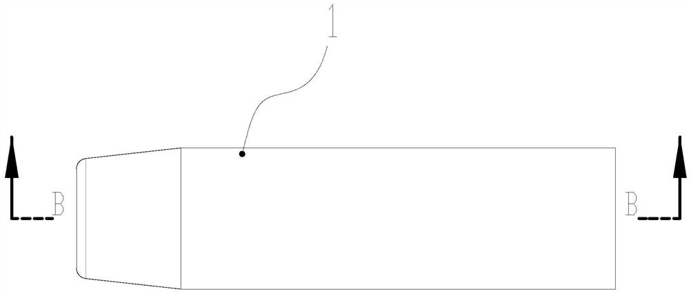
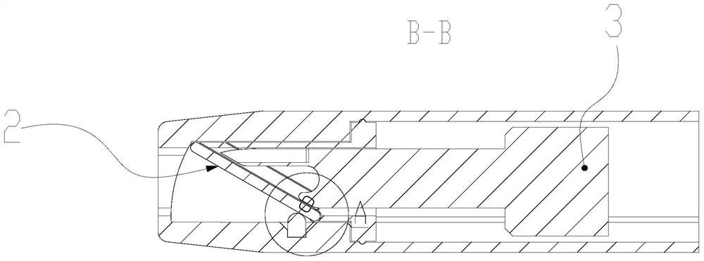
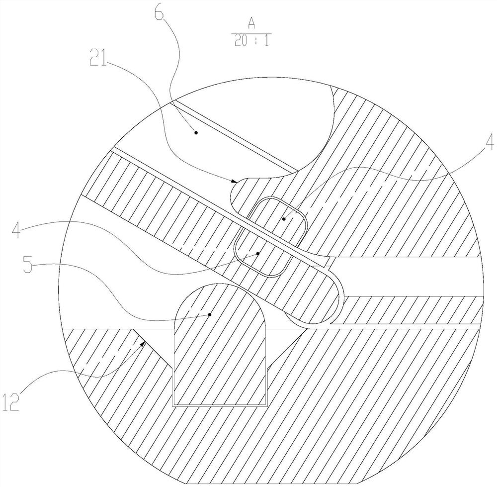
[0047] Such as Figures 1 to 4 The shutter structure for a pen shown includes an outer rod 1 , a shutter 2 and a writing body 3 . The above-mentioned shutter 2 is installed in the outer rod 1 and forms a hinge connection with the outer rod 1 . The above-mentioned writing body 3 is provided with an ejecting portion 21 , and a reset member 5 is also provided between the above-mentioned shutter 2 and the outer rod 1 . Both the ejecting portion 21 and the shutter 2 are provided with a magnetic end 4 .

[0048] When the core is retracted: the above-mentioned writing body 3 is located in the sealed chamber formed by the outer rod 1 and the shutter 2, and the above-mentioned shutter 2 is affected by the reset member 5 and the magnetic end 4, and maintains a normal state inward, so as to be inward with the outer rod 1. maintain a sealed relationship.

[0049]When the core is ejected: the ejector part 21 pushes the shutter 2, and the shutter 2 is turned down, so that the writing bod...

Embodiment 2

[0060] Such as Figure 5 A shutter structure for a pen is shown, including an outer rod 1 , a shutter 2 and a writing body 3 . The above-mentioned shutter 2 is installed in the outer rod 1 and forms a hinge connection with the outer rod 1 . The writing body 3 is provided with an ejection portion 21 , and the ejection portion 21 and the shutter 2 are provided with a magnetic attraction end 4 , and the magnetic attraction ends 4 are magnetically attracted to each other.

[0061] When the core is retracted: the above-mentioned writing body 3 is located in the sealed chamber formed by the outer rod 1 and the shutter 2, and the above-mentioned shutter 2 is affected by the magnetic suction end 4 and maintains a normal state inward, thereby maintaining a sealed relationship with the outer rod 1 .

[0062] When the core is ejected: the ejector part 21 pushes the shutter 2, and the shutter 2 is turned down, so that the writing body 3 is convenient to expose the outer rod 1.

[0063]...


PUM


Abstract

The invention relates to a shutter structure, in particular to a shutter structure for a pen. The shutter structure comprises an outer rod, a shutter and a writing main body, the shutter is arranged in the outer rod and is hinged and matched with the outer rod; an ejection part is arranged on the writing main body, magnetic attraction ends are arranged on the ejection part and the shutter, and the magnetic attraction ends are magnetically attracted with each other; when the core is collected, the writing main body is located in a sealed cavity formed by the outer rod and the shutter, and the shutter is influenced by the magnetic attraction ends and keeps an inward normal state, so that the shutter and the outer rod are kept in a sealed relation; when the core is discharged, the ejection part pushes the shutter open, and the shutter is turned downwards, so that the writing main body is conveniently exposed out of the outer rod; and by further excavating the structure relation of the shutter and accurately controlling the inclination angle of the shutter, the installation cost and complexity are reduced to the maximum extent, and meanwhile the sealing effect and the requirements for the magnetic attraction ends and the reset piece can be improved.

Description

technical field [0001] The invention relates to a shutter structure, in particular to a shutter structure for a pen. Background technique [0002] Now with the development of the times, more and more good operating structures for pens have surfaced, such as: CN201910318066.8 A new operating structure such as a twisting and locking pen has appeared, and these structures are also suitable for highlighters It is a product commonly used in the field of pens like fountain pens; however, highlighters and fountain pens have certain limitations, and their ink or ink will dry and must be sealed; while existing highlighters use Although the design of the shutter sealing structure is ingenious, due to structural reasons, the required diameter is relatively large, and the technology is mastered by foreigners; how to break through the technical blockade of foreigners while reducing the minimum diameter requirements, so that the final product is more in line with consumers' needs Practic...

Claims


Application Information

Patent Timeline
Patent Type & Authority Applications(China)
IPC IPC(8): B43K5/17
CPCB43K5/17
Inventor 宋迎迎
Owner 温州市简系文具有限公司
Learn More