Multi-stage ladder tooth type mixer for integrated afterburner

A technology of afterburner and mixer, applied in the direction of combustion chamber, continuous combustion chamber, combustion method, etc., can solve the problems of affecting the combustion efficiency of the afterburner, affecting the thrust performance of the engine, and keeping the total pressure loss high. Achieve the effect of improving thermal mixing efficiency, suppressing noise, and reducing total pressure loss

Active Publication Date: 2022-02-18
XIAMEN UNIV
View PDF13 Cites 0 Cited by
  • Summary
  • Abstract
  • Description
  • Claims
  • Application Information

AI Technical Summary

Problems solved by technology

[0003] The airflow entering the afterburner is generally mixed with the internal gas and external air through the mixer. The mixing effect will largely affect the combustion efficiency of the afterburner and thus affect the thrust performance of the engine.
Most of the mixers used in the traditional afterburner are lobe mixers and annular mixers. The lobe mixer has a better mixing effect, but it will cause a large pressure loss and poor structural rigidity, so it is suitable for Engines with high bypass ratio
The total pressure loss of the annular mixer is very small, but the air flow mixing only depends on the shearing action between the inner and outer air streams, and the mixing effect is very unsatisfactory
[0004] In recent years, relevant work on afterburner mixers has been carried out at home and abroad, and the concept of multi-stage mixers has been proposed internationally. The mixing efficiency of internal and external content has been greatly improved, but the problem of high total pressure loss has not been resolved

Method used


Image

  • Multi-stage ladder tooth type mixer for integrated afterburner
  • Multi-stage ladder tooth type mixer for integrated afterburner
  • Multi-stage ladder tooth type mixer for integrated afterburner

Examples


Embodiment Construction

[0021] The following embodiments will further illustrate the present invention in conjunction with the accompanying drawings.

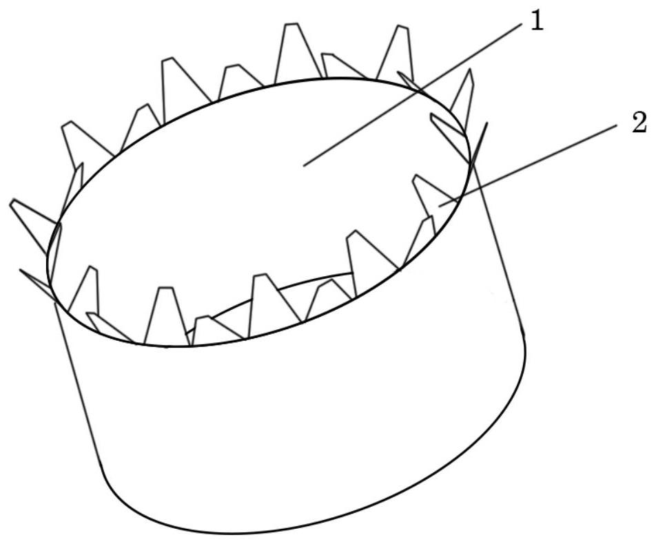
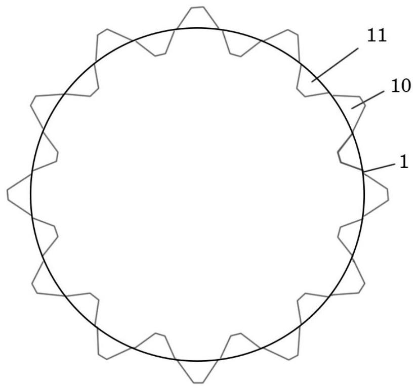
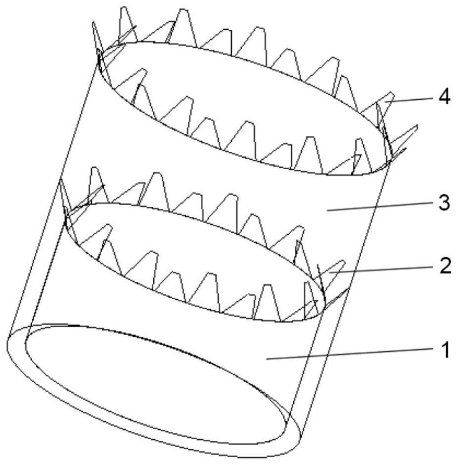
[0022] The multi-stage ladder-toothed mixer described in the embodiment of the present invention includes two-stage mixing sections, and each stage of mixing section is composed of ladder-toothed crown mixers of different sizes, figure 1 with 2 It is a three-dimensional view and a top view of the stepped tooth mixer in the primary mixing section of the embodiment of the present invention. The ladder-tooth crown mixer is composed of closely arranged inner and outer inclined ladder teeth on the outlet end face of the mixing section of each stage. When the gas flows through these staggered ladder teeth structures, it induces a flow direction vortex, which strengthens the internal and external duct flow. Blend. The structure of the first-stage blending section is similar to that of the ladder tooth mixer in the second-stage blending section. Such as ...


PUM


Abstract

The invention discloses a multi-stage ladder tooth type mixer for an integrated afterburner, and relates to an aero-engine afterburner. Two stages of mixing sections are arranged, each stage of mixing section is composed of ladder tooth crown-shaped mixers of different sizes, the mixing sections are of an annular structure, the mixing sections are sequentially named as the first-stage mixing section and the second-stage mixing section according to the flowing sequence of outer culvert airflow, and the first-stage mixing section is arranged in the second-stage mixing section; and each stage of mixing section is composed of an inner wall and a ladder tooth crown-shaped mixer, inwards-inclined ladder teeth and outwards-inclined ladder teeth of the ladder tooth crown-shaped mixer are alternately and evenly arranged on the end face of an outlet of each stage of mixing section, when gas flows through the inwards-inclined ladder teeth and the outwards-inclined ladder teeth, the ladder teeth distributed in a staggered mode induce a flow direction vortex, a stable and uniform mixing area is formed at the rear end of the ladder tooth crown-shaped mixer, and mixing of airflow of the inner duct and the outer duct is enhanced. Noise generation is effectively restrained, air flow mixing of inner and outer ducts of an aero-engine is effectively enhanced, mixing efficiency is improved, total pressure loss is reduced, and therefore combustion efficiency of an afterburner is improved.

Description

technical field [0001] The invention relates to an afterburner of an aero-engine, in particular to a multi-stage stepped tooth mixer for an integrated afterburner. Background technique [0002] The afterburner is generally used on aero engines, located between the turbine and the tail nozzle, to increase engine thrust and aircraft flexibility. The main structure of afterburner includes mixing diffuser, oil supply device, flame stabilizer, igniter, anti-vibration heat shield and afterburner cylinder, etc. After fuel injection and combustion in the main combustion chamber, there is still a large amount of oxygen in the air, so fuel is injected again in the afterburner, and fresh air is introduced through the mixer at the same time, and the combustion is carried out again, releasing a large amount of heat, which greatly improves the thrust performance of the aircraft. . [0003] The airflow entering the afterburner usually mixes the internal gas and external air through the m...

Claims


Application Information

Patent Timeline
Patent Type & Authority Applications(China)
IPC IPC(8): F23R3/28
CPCF23R3/286
Inventor 黄玥刘润富尤延铖
Owner XIAMEN UNIV
Why Eureka
Try Eureka