Nitrogen oxide mixing treatment device

A technology of mixed treatment and nitrogen oxides, which is applied in mufflers, exhaust treatment, exhaust devices, etc., can solve the problems of poor catalytic effect, insignificant effect, uneven mixing of ammonia gas, etc., to improve the uniformity of the flow field and anti-urea crystallization ability, improve catalytic reaction efficiency, improve the effect of induction efficiency

Pending Publication Date: 2022-02-22
三河市科达科技有限公司
View PDF0 Cites 1 Cited by
  • Summary
  • Abstract
  • Description
  • Claims
  • Application Information

AI Technical Summary

Problems solved by technology

[0003] There are many forms of selective nitrogen oxide reactor mixers: for example, direct mixing, the engine exhaust gas is discharged into the selective nitrogen oxide reactor, directly mixed with the ammonia gas decomposed from the urea solution sprayed from the urea nozzle, and then enters In the nitrogen oxide reactor, the reaction is carried out under the action of the catalyst in the carrier; there are also other forms of mixers, such as adding a perforated plate to the front of the mixer, etc., such effects are not obvious; and there are exhaust gases from the engine. Nitrogen oxides are mixed unevenly with the ammonia gas decomposed from the urea solution sprayed out of the nozzle, and the mixing efficiency is low. In addition, the mixed particles are large in size. After entering the carrier, the contact area with the catalyst is small, the reaction efficiency is low, and the catalytic effect is not good. In addition, ammonia leakage is relatively serious, and urea is easy to crystallize

Method used


Image

  • Nitrogen oxide mixing treatment device
  • Nitrogen oxide mixing treatment device
  • Nitrogen oxide mixing treatment device

Examples


Embodiment 1

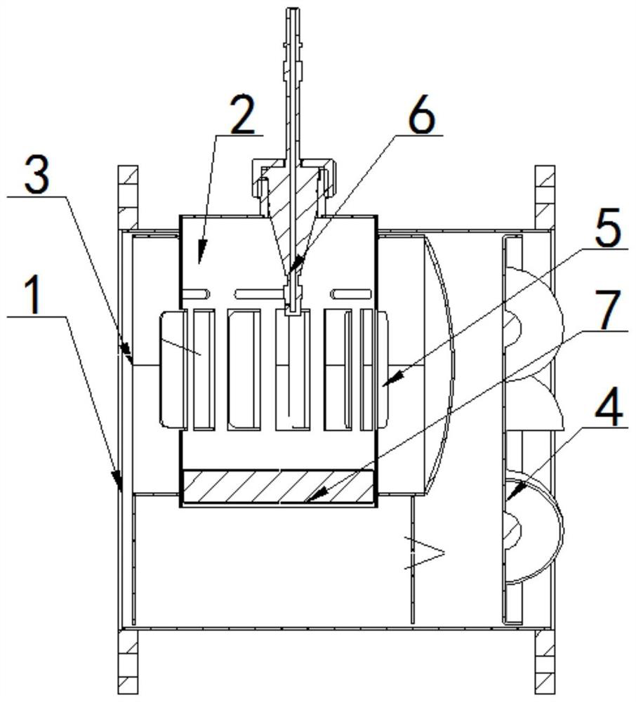
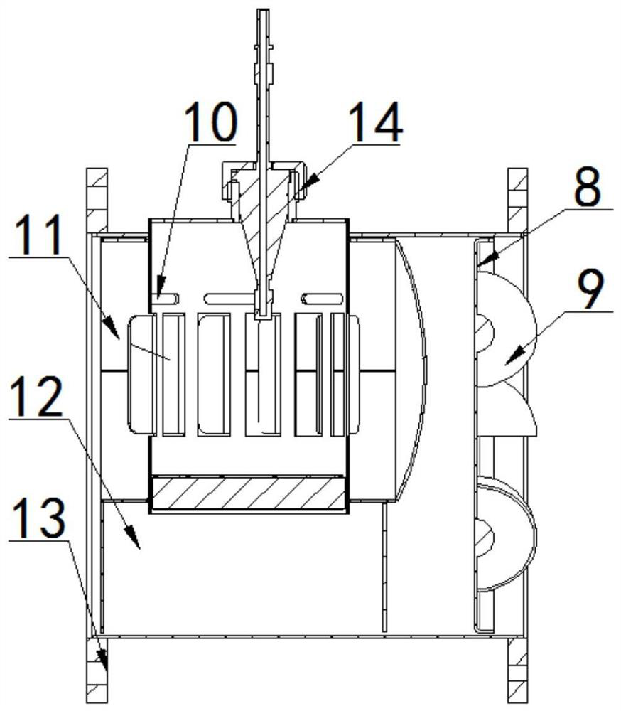
[0023] A nitrogen oxide mixing treatment device, comprising: a hollow outer casing 1 and a mixer 2 arranged in the outer casing 1; an air inlet 3 is provided on the outer casing 1 relatively close to the mixer 2, so The end of the outer casing 1 relatively far away from the mixer 2 is provided with a cyclone structure 4, and the cyclone structure 4 is used for uniform gas and flow diversion;

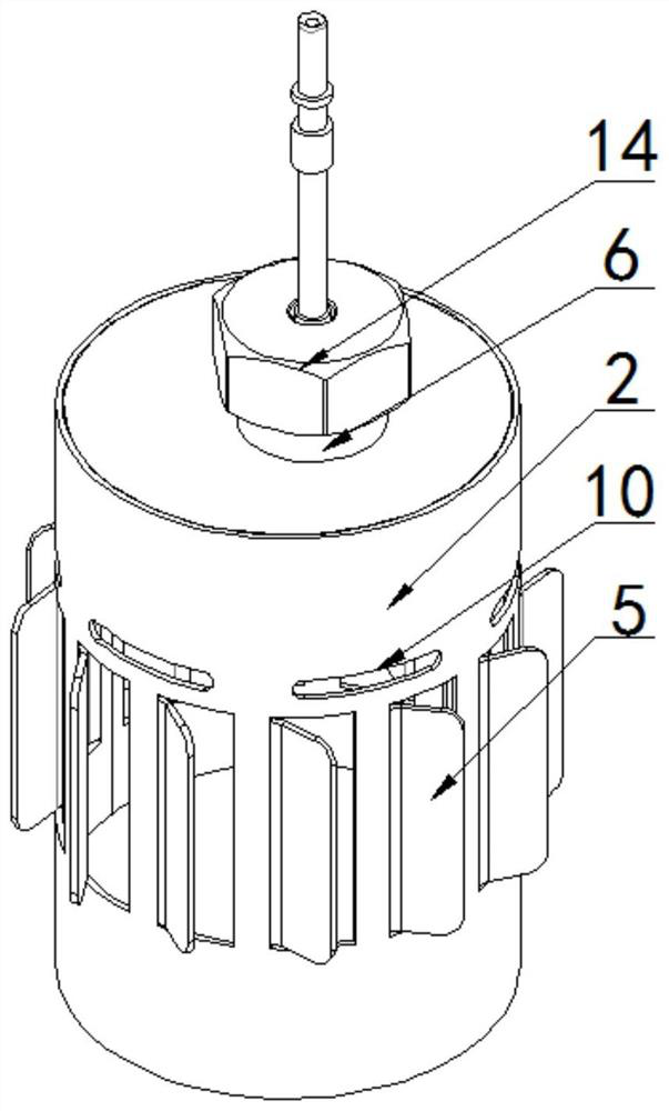
[0024] The interior of the mixer 2 is hollow, and the side wall of the mixer 2 is provided with several spaced first through holes, and the edge of the first through holes is provided with a guide plate 5 facing the inner wall of the outer casing 1; The upper end of the outer casing 1 is vertically provided with a through nozzle 6 , which faces the interior of the mixer 2 and is used for injecting reactants; the inner lower end of the mixer 2 is provided with a filter screen 7 for decomposing gas particles.

[0025] When using this device, if figure 1 As shown, firstly, the automobile e...


PUM


Abstract

The invention discloses a nitrogen oxide mixing treatment device. The nitrogen oxide mixing treatment device comprises a hollow outer shell and a mixer arranged in the outer shell, wherein a gas inlet is formed in one end, relatively close to the mixer, of the outer shell, a cyclone structure is arranged at one end, relatively far away from the mixer, of the outer shell, and the cyclone structure is used for uniformizing gas and guiding flow; the interior of the mixer is hollow, a plurality of first through holes are formed in the side wall of the mixer at intervals, and guide plates facing the inner wall of the outer shell are arranged at the edges of the first through holes; a through nozzle is vertically arranged at the upper end of the outer shell, faces the interior of the mixer and is used for injecting reactants; and a filter screen for decomposing gas particles is arranged at the lower end in the mixer. According to the nitrogen oxide mixing treatment device, the catalytic reaction efficiency of nitrogen oxides is improved, and the ammonia gas leakage problem is controlled; and the exhaust resistance is reduced, the exhaust back pressure is reduced, the flow field uniformity and the urea crystallization resistance are improved, and the working efficiency is improved.

Description

technical field [0001] The present disclosure generally relates to the technical field of tail gas treatment, and specifically relates to a nitrogen oxide mixed treatment device. Background technique [0002] Environmental governance is an important issue in the current world development, and environmental pollution has endangered people's health. For fuel engines, especially those that use diesel as raw material, the pollutants emitted by the exhaust gas of the engine will seriously pollute the atmospheric environment before being treated. These standards, and achieve the purpose of controlling air pollution. An important index for the control of engine exhaust emissions is the control of the emission limit of nitrogen oxides. The control of nitrogen oxide emission targets is accomplished through selective nitrogen oxide reactors. [0003] There are many forms of selective nitrogen oxide reactor mixers: for example, direct mixing, the engine exhaust gas is discharged int...

Claims


Application Information

Patent Timeline
Patent Type & Authority Applications(China)
IPC IPC(8): F01N3/28F01N3/20F01N13/18
CPCF01N3/2892F01N3/2073F01N13/1855F01N2570/14F01N2610/02F01N2610/1453
Inventor 李会利苏继龙
Owner 三河市科达科技有限公司
Why Eureka
Try Eureka