Gas injector with multiple valve needles

A gas injector and valve needle technology, applied in fuel injection devices, special fuel injection devices, machines/engines, etc., can solve problems such as wear and tear, and achieve the effect of small injection rate

Pending Publication Date: 2022-02-22
ROBERT BOSCH GMBH
View PDF0 Cites 0 Cited by
  • Summary
  • Abstract
  • Description
  • Claims
  • Application Information

AI Technical Summary

Problems solved by technology

[0003] Another problem area in gas injectors is fundamentally that, since the medium is gaseous, it cannot be lubricated by the medium itself, as...

Method used


Image

  • Gas injector with multiple valve needles
  • Gas injector with multiple valve needles
  • Gas injector with multiple valve needles

Examples


Embodiment Construction

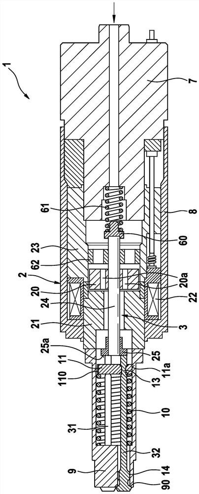
[0033] Below, refer to the attached Figures 1 to 4 , to describe in detail the gas injector 1 according to the first preferred embodiment of the present invention.

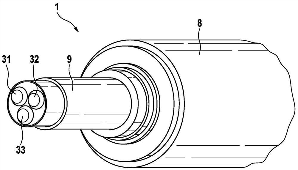
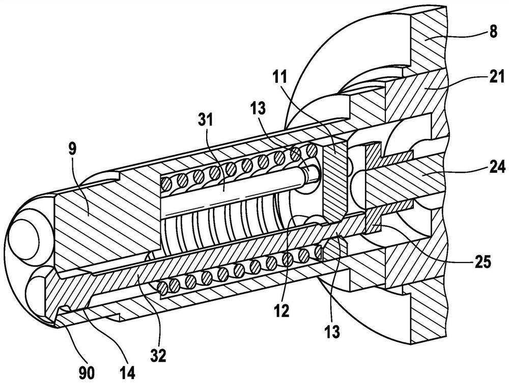
[0034] as from figure 1 As can be seen in the figure, a gas injector 1 for introducing gaseous fuel comprises an electromagnetic actuator 2 , which actuates three valve needles via an actuating unit 3 . as from figure 2 It can be seen that a first valve needle 31 , a second valve needle 32 and a third valve needle 33 are provided. The three valve needles are each arranged at a distance of 120° in the circumferential direction.

[0035] The three valve needles 31, 32, 33 are outwardly opening valve needles and as shown by figure 2 It can be seen that there are valve discs respectively. In this case, the valve disks of the valve needles 31 , 32 , 33 each have the same diameter.

[0036] Electromagnetic actuator 2 includes an armature 20 , which bears against three valve needles 31 , 32 , 33 by means of an a...


PUM


Abstract

The invention relates to a gas injector for injecting gas, in particular directly into a combustion chamber of an internal combustion engine. The gas injector comprises: an electromagnetic actuator (2) having an armature (20), an inner pole (21) and a coil (22); at least two outwardly open valve needles (31, 32, 33), each of which releases and closes a flow opening of the gas path on the valve seat (90); a reset device (10), which is provided for resetting the valve needle (31, 32, 33) into its initial position.

Description

technical field [0001] The invention relates to a gas injector for injecting gaseous fuels, especially hydrogen or natural gas or the like, with improved injection properties. The gas injector is designed in particular for direct injection into the combustion chamber of the internal combustion engine. Background technique [0002] Gas injectors of various designs are known from the prior art. Gas injectors that inject directly into the combustion chamber are usually designed as outwardly opening injectors, since this type of injector construction makes sense because the high combustion pressure in the combustion chamber assists the open valve needle during closing . Compared to injectors for liquid fuels, such as gasoline injectors, gas injectors based on gaseous media have a significantly larger valve seat cross section. Only then can the gaseous fuel be injected into the combustion chamber in sufficient quantities. [0003] A further problematic area in gas injectors i...

Claims


Application Information

Patent Timeline
IPC IPC(8): F02M21/02F02M63/00F02M61/10F02M51/06
CPCF02M21/0263F02M21/0254F02M63/0001F02M61/10F02M51/0625F02M21/0206F02M21/0215F02M21/0269Y02T10/30F02M51/0653F02M63/0015F02M2200/16
Inventor M·米勒M·伯厄
Owner ROBERT BOSCH GMBH
Why Eureka
Try Eureka