Device and method for controlling internal combustion engine

a technology of internal combustion engine and control device, which is applied in the direction of electric control, machines/engines, mechanical equipment, etc., can solve the problems of evaporation and fuel mixture deterioration, combustion deterioration, and generation of smoke in the high load region, and achieves superior smoke suppression, long injection time period, and small injection rate

Active Publication Date: 2018-03-06
NISSAN MOTOR CO LTD
View PDF57 Cites 1 Cited by
  • Summary
  • Abstract
  • Description
  • Claims
  • Application Information

AI Technical Summary

Benefits of technology

[0012]Accordingly, even when the fuel injection start timing is set to a timing before the exhaust upper dead center so that the fuel injection period crosses the exhaust upper dead center, the smoke is hard to be generated. It is possible to permit a relatively long injection time period without excessively retarding the fuel injection end timing. Consequently, it is possible to use the fuel injection valve having a small injection rate.
[0013]Moreover, in a case where the variable compression ratio mechanism is a multi-link piston crank mechanism having a small piston rising (ascending) speed near the upper dead center, the relative speed of the piston with respect to the spraying becomes small. The collision with the piston crown surface is further relieved. This is further superior in the suppression of the smoke.
[0014]By this invention, the relatively long injection period can be permitted without excessively retarding the fuel injection end timing at the high load, and to use the fuel injection valve having the small injection rate.

Problems solved by technology

The evaporation and the mixture of the fuel is deteriorated.
This becomes the cause for the generation of the smoke in the high load region.
As described in the patent document 1, in a case where the fuel injection end timing is excessively retarded at the high load, it is not possible to ensure the time necessary for the mixture and the evaporation of the fuel spraying, so that the combustion is deteriorated.
On the other hand, in a case where the fuel injection start timing is closer to the exhaust upper dead center, the smoke is increased by the collision and the adhesion of the fuel on the piston.
However, when the injection rate of the fuel injection valve is large, the injection period (that is, the opening period of the fuel injection valve) becomes excessively short when the fuel injection amount is small.

Method used


Image

  • Device and method for controlling internal combustion engine
  • Device and method for controlling internal combustion engine
  • Device and method for controlling internal combustion engine

Examples


Embodiment Construction

[0018]Hereinafter, one embodiment according to the present invention is illustrated in detail based on the drawings.

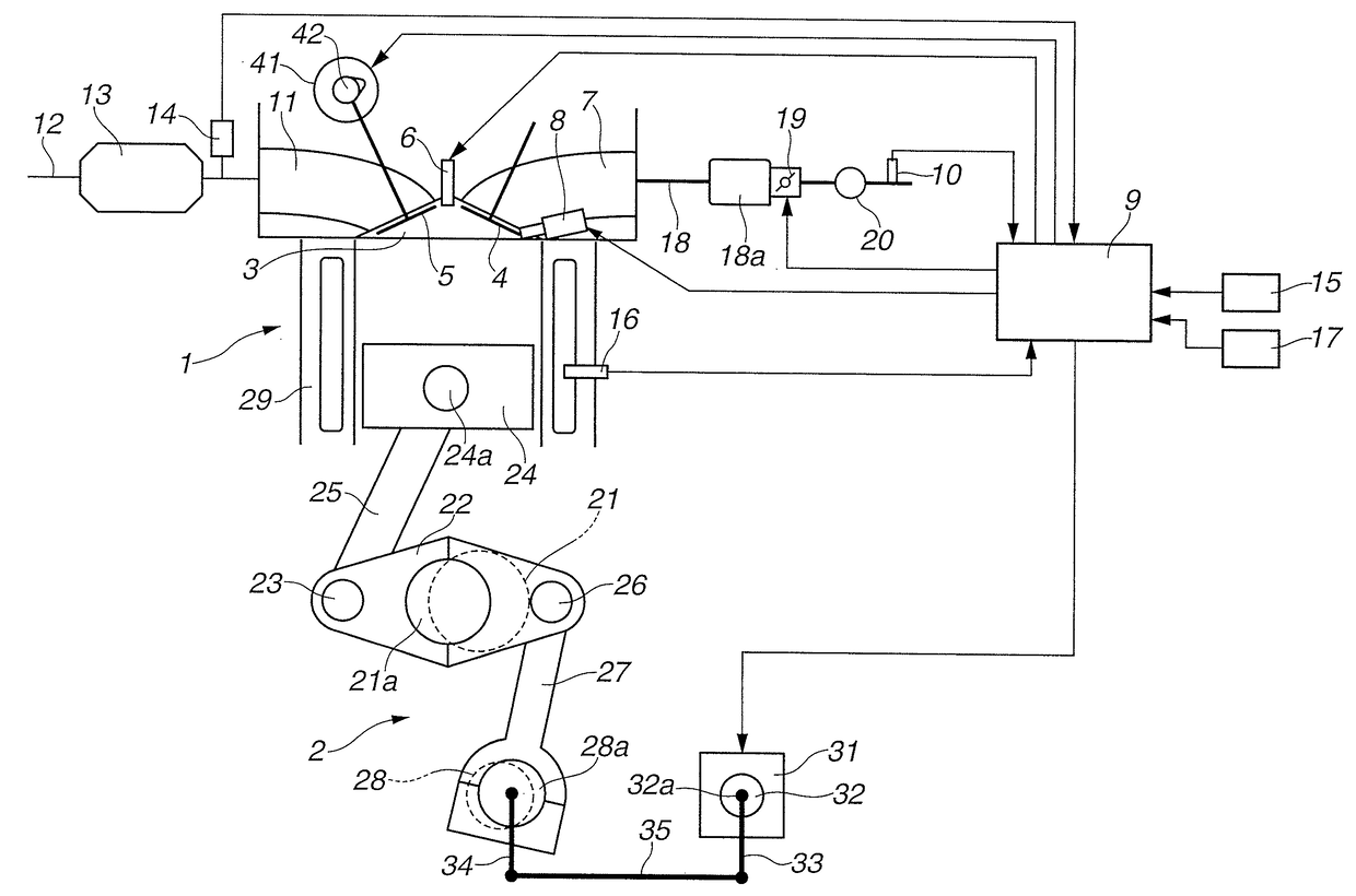
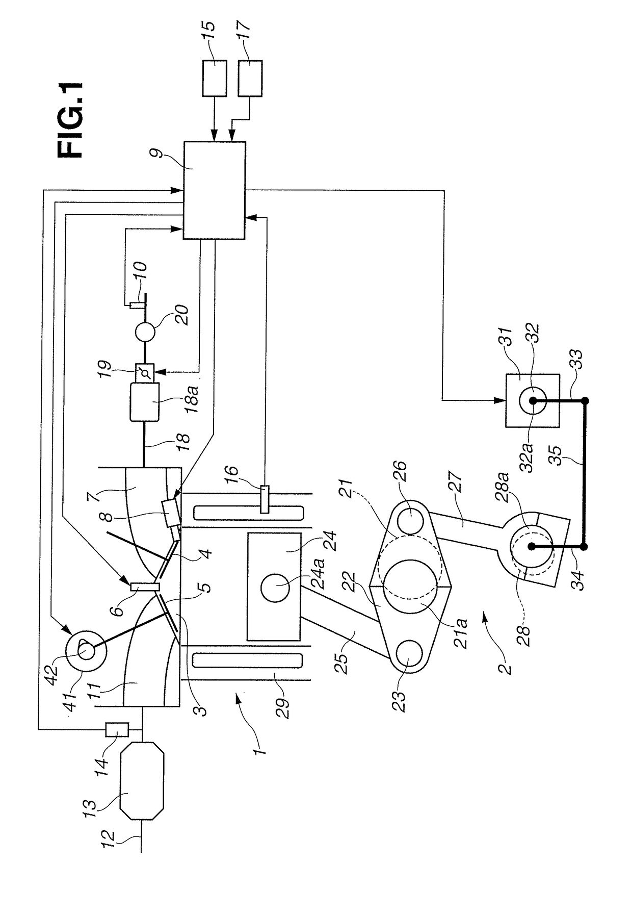
[0019]FIG. 1 shows a system configuration of a vehicular internal combustion engine 1 to which the present invention is applied. This internal combustion engine 1 is a cylinder direct injection type ignition internal combustion engine which is a four stroke cycle engine, which is provided with a turbocharger, and which is provided with a variable compression ratio mechanism 2 that uses a multi-link type piston crank mechanism. A pair of intake valves 4 and a pair of exhaust valves 5 are disposed on a wall surface of a ceiling (top surface) of a combustion chamber 3. An ignition plug 6 is disposed at a central portion surrounded by these intake valves 4 and exhaust valves 5.

[0020]A fuel injection valve 8 is disposed below an intake port 7 arranged to be opened and closed by the intake valve 4. The fuel injection valve 8 is arranged to directly inject the fuel within the...


PUM


Abstract

A control device for an internal combustion engine including a variable compression ratio mechanism arranged to vary a relative position relationship between a piston and a cylinder, and thereby to vary a mechanical compression ratio, and a fuel injection valve arranged to directly inject a fuel within a combustion chamber, the control device includes: at least in an engine high load region including a full open, the compression ratio at an exhaust upper dead center being controlled to a low compression ratio, a fuel injection start timing of the fuel in which an air-fuel mixture is formed within the combustion chamber, and which is ignited by an ignition plug being set before an exhaust upper dead center so that a fuel injection period crosses an upper dead center.

Description

TECHNICAL FIELD[0001]This invention relates to an internal combustion engine arranged to directly inject a fuel into a combustion chamber, and to ignite a generated mixture air by an ignition plug, more specifically to a control device and a control method for an internal combustion engine provided with a variable compression ratio mechanism.BACKGROUND ART[0002]Conventionally, there are known various types of variable compression ratio mechanisms arranged to vary a mechanical compression ratio of an internal combustion engine. For example, the present applicant and so on make many proposals of the variable compression ratio mechanisms arranged to vary a geometry of a multi-link piston crank mechanism. Furthermore, there is known a variable compression ratio mechanism arranged to displace a position of the cylinder in the upward and downward directions with respect to a center position of the crank shaft.[0003]On the other hand, there is known a spark ignition internal combustion eng...

Claims


Application Information

Patent Timeline
Patent Type & Authority Patents(United States)
IPC IPC(8): F02D41/34F02M61/04F02M45/00F02D15/02F02M61/14F02B75/04F02P15/06F02D41/00F02D41/40F02D41/38
CPCF02D41/345F02B75/048F02D15/02F02D41/401F02M45/00F02M61/14F02P15/06F02M61/04Y02T10/44F02D41/40F02D2041/001F02D2041/389Y02T10/40
Inventor MANO, TADAKIONODA, NAONORI
Owner NISSAN MOTOR CO LTD
Why Eureka
Try Eureka