Fuel tank

Inactive Publication Date: 2005-05-26
HONDA MOTOR CO LTD
View PDF68 Cites 41 Cited by
  • Summary
  • Abstract
  • Description
  • Claims
  • Application Information

AI Technical Summary

Benefits of technology

[0029] As described above, since the filter is formed of the fluororesin element, and the filter is disposed in such a manner as to be held by the division surfaces of the upper tank member and the lower tank member when the upper tank member is joined to the lower tank member, the filter can be firmly fixed by a simple configuration. Thus, the need for a supporting member for mounting the filter is eliminated, and product and production costs can be greatly reduced.
[0030] Since the filter is provided in a location where it can be seen from the filler port, water accumulated in the filter can be easil

Problems solved by technology

If water covers the filter 205, the water film will exert a blocking effect, preventing passage of fuel, and making smooth filtration impossible.
However, water contained in the fuel cannot be separated.
Fuel contaminated with water accumulates in the fuel tank, or can cause the problem that it enters an engine and its induction system.
However, it is not easy to detect

Method used


Image

  • Fuel tank
  • Fuel tank
  • Fuel tank

Examples


second embodiment

[0082] Now, the structure of a fuel tank will be described with reference to FIGS. 9 to 11.

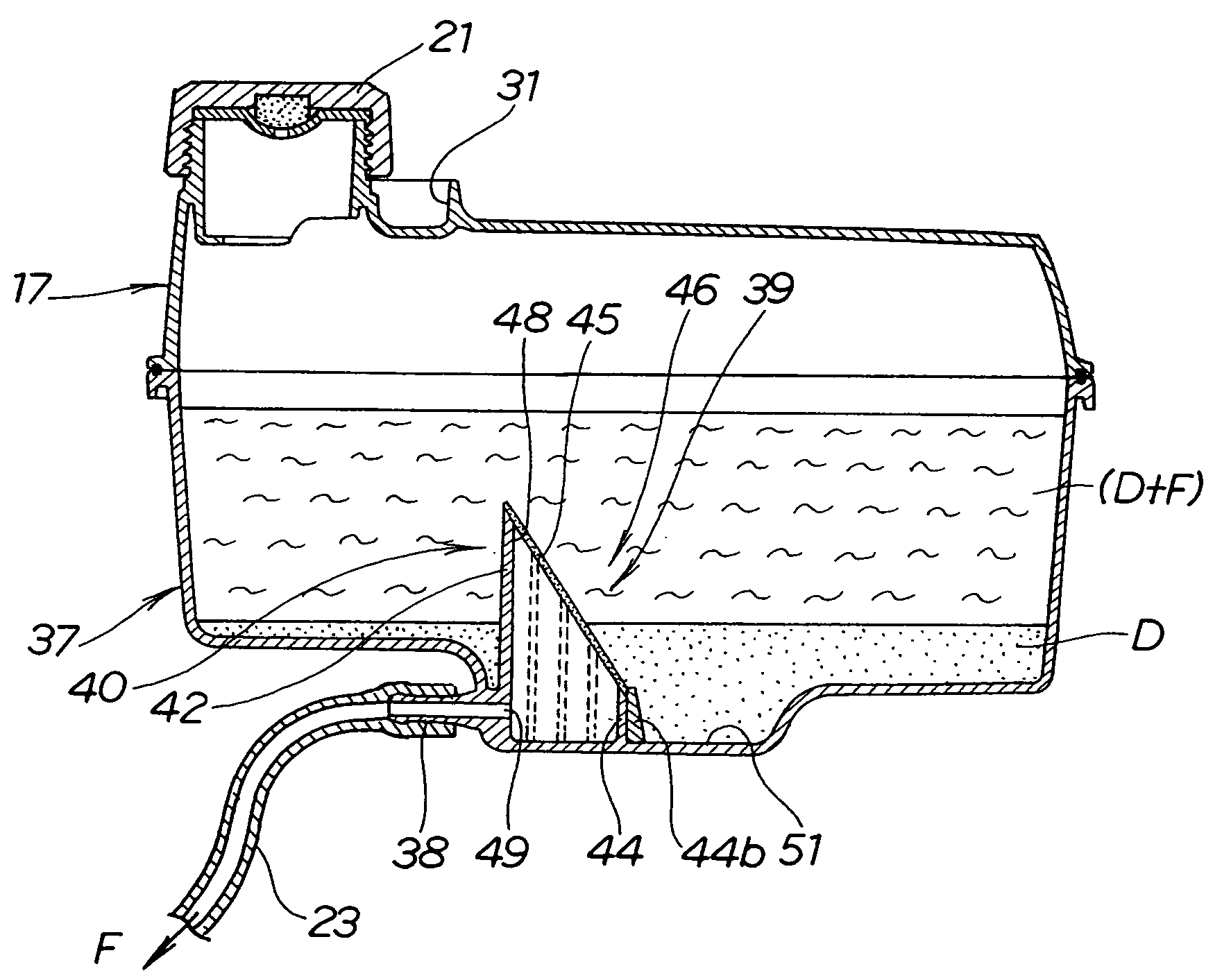
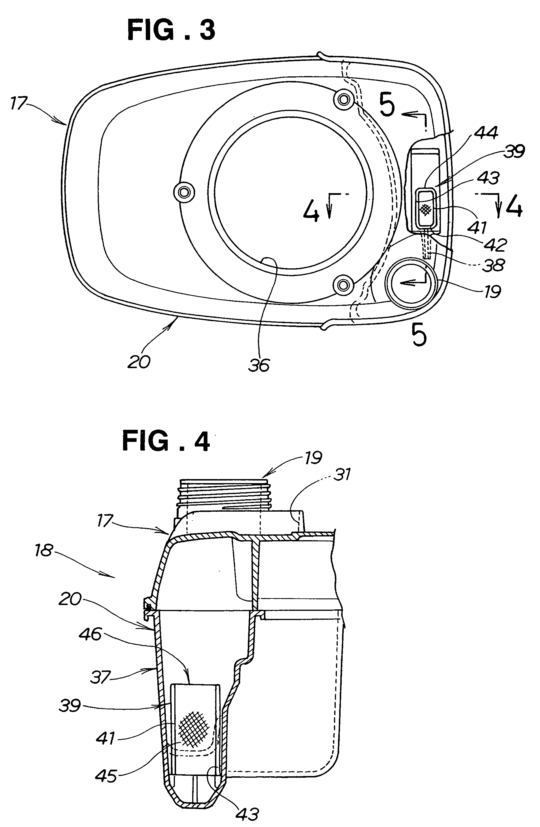
[0083] Referring to FIGS. 9 and 10, a fuel tank 18 of the second embodiment has a tank body 60. The tank body 60 consists of a fan shroud 17 doubling as an upper half of the tank body 60, and a fuel tank member 37 constituting a lower half. A lower peripheral edge of the fan shroud 17 is fixed to an upper peripheral edge of the fuel tank member 37. A fuel outlet port 38 is provided at the bottom of the fuel tank member 37.

[0084] The fuel tank 18 has the hollow tank body 60, a filler port 19 formed at the top of the tank body 60, a fuel introducing passage 61 extending from the filler port 19 inwardly of the tank body 60, and a filter 62 provided midway along the fuel introducing passage 61. The filter 62 includes a fluororesin element 65 having the property of not allowing water to pass through it but allowing fuel to pass through it. The element 65 is provided in a location where it can be ...

third embodiment

[0106] Now, the structure of a fuel tank will be described with reference to FIGS. 16 to 18.

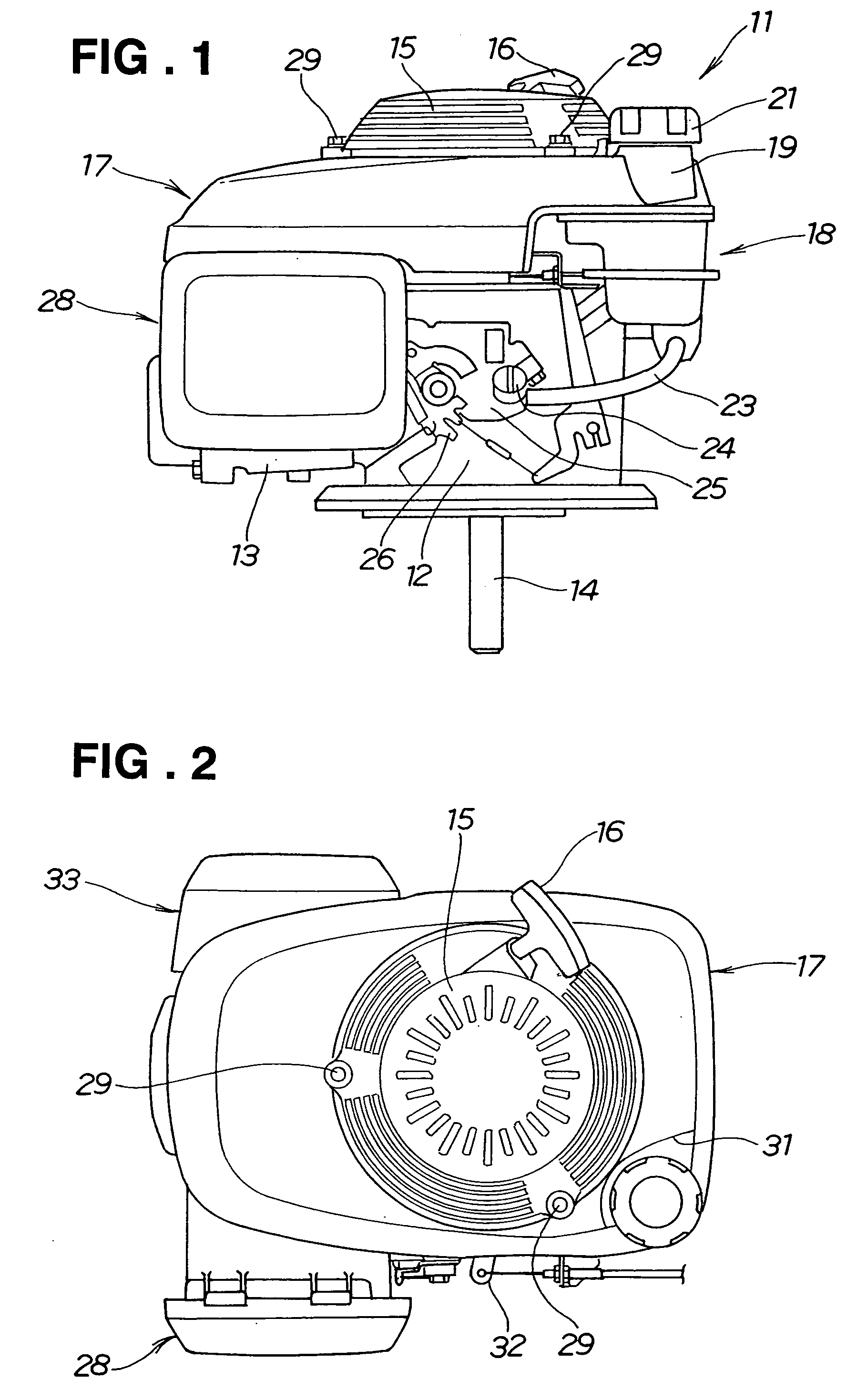
[0107]FIG. 16 illustrates an engine provided at its top with a fuel tank according to the third embodiment.

[0108] An engine 111 shown in FIG. 16 has a crankcase 112, a body 113 mounted on the crankcase 112 by bolting, a fuel tank 116 mounted on top of the body 113 via a tank bracket 114 and bolts and nuts 115a, 115b, a recoil starter 118 mounted to the body 113, and a starter grip 119 attached to the recoil starter 18 via a string. Reference numeral 117 denotes a fuel cock lever.

[0109] As shown in FIG. 17, the fuel tank 116 has a tank body 120. The tank body 120 consists of an upper tank member 121 and a lower tank member 122 joined to the upper tank member 121. A filler port 123 is provided at an upper surface 121a of the upper tank member 121, and a cap 124 is attached to the filler port 123.

[0110] A fuel outlet port 125 is provided at the lower tank member 122, and a filter 126 for fil...


PUM


Abstract

A fuel tank used for a general-purpose engine is provided. The fuel tank includes a tank body for storing fuel. A filter for separating fuel containing water into fuel and water is provided in a fuel passage within the tank body. The filter includes a fluororesin element having the property of not allowing water to pass through it but allowing fuel to pass through it.

Description

FIELD OF THE INVENTION [0001] The present invention relates to fuel tanks with a filter for separating foreign matter such as water and dirt in fuel. BACKGROUND OF THE INVENTION [0002] A fuel tank with a filter formed of a fluororesin element has conventionally been known (e.g., see Japanese Utility Model Laid-Open Publication No. HEI-4-123364). The fuel tank disclosed in this publication will be described with reference to FIG. 21. [0003] Referring to FIG. 21, an overflow passage 202 is formed around a filler cap 201. In a portion connecting the overflow passage 202 to a fuel tank 203 is provided a fuel reservoir 204 for temporarily holding fuel overflowing through a fluororesin filter 205. The overflow passage 202 has a drain hole 206 through which to let rainwater out. [0004] Fuel overflowed when fuel is fed into the fuel tank 203 is separated by the fluororesin filter 205 into water and fuel. Fuel passes through the filter 205 and is collected through the fuel reservoir 204 in t...

Claims


Application Information

Patent Timeline
IPC IPC(8): B01D17/00B01D35/027B01D36/00B01D39/16F02M37/00F02M37/22
CPCB01D17/00B01D35/027B01D36/003B01D39/1623F02M37/0082F02M37/221B01D17/08B01D17/10F02M37/26F02M37/34F02M37/50
Inventor FUJITA, YASUSHISUZUKI, TAKASHIARAI, TETSUYAOGAWA, KAZUHISA
Owner HONDA MOTOR CO LTD
Why Eureka
Try Eureka