
Connector and pipe taking device

A technology for connecting joints and outer pipes, applied in the field of connecting joints and pipe taking devices, can solve the problems of easy loosening of nuts, leakage at joints, leakage at joints, etc., and achieves the effects of good fixing effect and convenient installation and disassembly.

Pending Publication Date: 2022-02-25
RIFENG ENTERPRISE FOSHAN CO LTD +2
View PDF0 Cites 0 Cited by
  • Summary
  • Abstract
  • Description
  • Claims
  • Application Information

AI Technical Summary

Problems solved by technology

[0002] At present, a large number of pipes are used in the fields of water supply and drainage, gas, etc. These pipes need to be connected by joints. The existing pipe joints usually adopt clamping type, flared sliding type and nut ferrule type, etc. However, there are certain disadvantages in the above-mentioned connection methods: 1. The clamp type joint and the flared sliding joint need professional plumbers to use special tools for installation, which is highly professional and cumbersome and complicated to operate. The joint leaks, and since the joint cannot be disassembled and reused after installation, if the joint leaks, the pipe can only be cut short, which makes the length of the pipe shorter, and new pipes and joints need to be re-laid, which is time-consuming, laborious and expensive. ;2. The nut ferrule type joint needs to be installed with a wrench to tighten the nut, so there is a requirement for the installation space, and a wrench position needs to be reserved. There are certain installation limitations, and the nut is easy to loose after a period of use, which will cause leakage at the connection leak

Method used


Image

  • Connector and pipe taking device
  • Connector and pipe taking device
  • Connector and pipe taking device

Examples


Embodiment Construction

[0037] The specific implementation manners of the present invention will be further described in detail below in conjunction with the accompanying drawings and embodiments. The following examples are used to illustrate the present invention, but are not intended to limit the scope of the present invention.

[0038] In the description of the present application, it should be understood that the terms "upper", "lower", "left", "right", "front", "rear", "inner", "outer", " "Top", "bottom", "circumferential", "center" and other indication orientations or positional relationships are based on the orientations or positional relationships shown in the drawings, and are only for the convenience of describing the present invention and simplifying the description, rather than indicating or implying Any device or element must have a specific orientation, be constructed and operate in a specific orientation and therefore should not be construed as limiting the invention. In addition, the...


PUM


Abstract

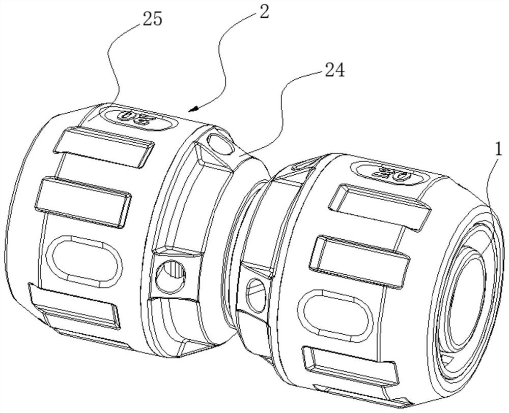
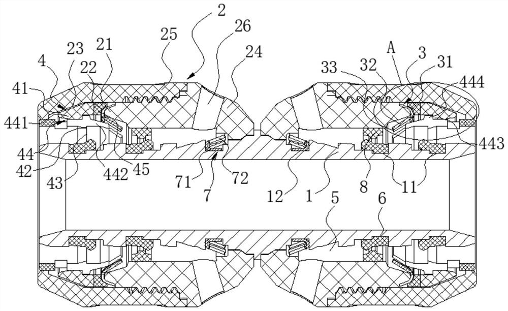
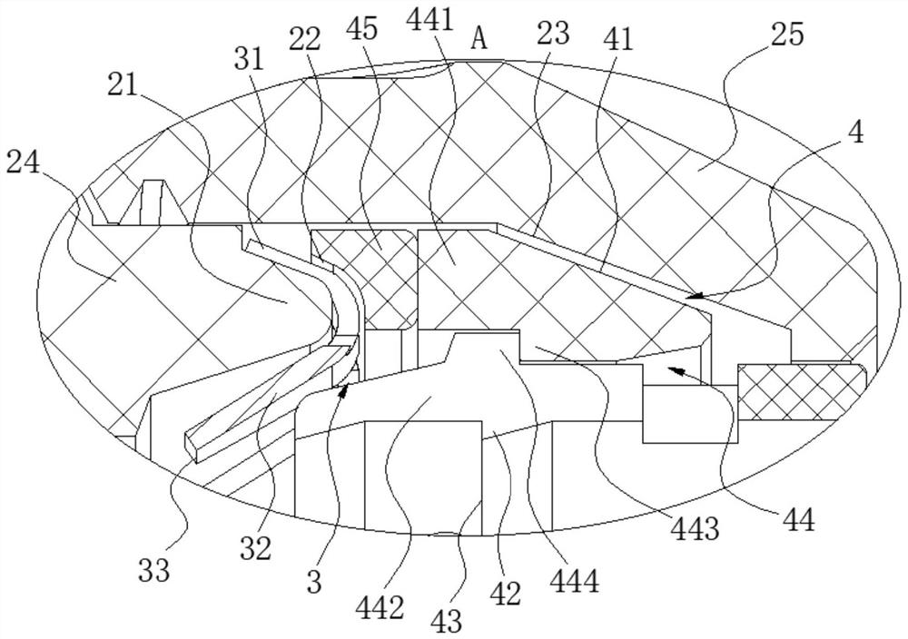
The invention relates to the field of pipe connection and disassembly, and discloses a connector and a pipe taking device. The connector comprises an inner pipe, an outer pipe, a first elastic claw ring and an elastic tightening ring; an annular insertion groove for inserting a pipe is defined between the inner pipe and the outer pipe; the first elastic claw ring is provided with a first inverted tooth piece; the elastic tightening ring is provided with an inverted tooth part; and a first clamping point and a second clamping point are defined by the inner pipe and the outer pipe respectively. The beneficial effects are that the first inverted tooth piece and the inverted tooth part extend inwards and gradually incline backwards from outside to inside, and smooth inserting connection is guaranteed when a pipe is inserted; when the pipe is subjected to outward disengaging force, the first inverted tooth piece and the inverted tooth part can clamp the pipe and prevent the pipe from disengaging from the annular insertion groove, so that the pipe is prevented from falling off from the annular insertion groove; and meanwhile, the pipe can be easily taken out through the pipe taking device, mounting and dismounting are convenient, and the fixing effect is good.

Description

technical field [0001] The invention relates to the field of pipe connection and disassembly, in particular to a connection joint and a pipe taking device. Background technique [0002] At present, a large number of pipes are used in the fields of water supply and drainage, gas, etc. These pipes need to be connected by joints. The existing pipe joints usually adopt clamping type, flared sliding type and nut ferrule type, etc. However, there are certain disadvantages in the above-mentioned connection methods: 1. The clamp type joint and the flared sliding joint need professional plumbers to use special tools for installation, which is highly professional and cumbersome and complicated to operate. The joint leaks, and since the joint cannot be disassembled and reused after installation, if the joint leaks, the pipe can only be cut short, which makes the length of the pipe shorter, and new pipes and joints need to be re-laid, which is time-consuming, laborious and expensive. ;...

Claims


Application Information

Patent Timeline
IPC IPC(8): F16L37/091
CPCF16L37/0915
Inventor 李茜民林细勇刁振彬邱帮龙何旺枝
Owner RIFENG ENTERPRISE FOSHAN CO LTD
Learn More