Flexible flat cable fitting device and fitting method based on Internet of Things

A technology of flexible wiring and laminating devices, which is applied in the direction of assembling printed circuits with electrical components, electrical components, and printed circuit manufacturing. , to achieve the effect of not easy to deviate and improve efficiency

Inactive Publication Date: 2022-02-25
南京秉昱科技有限公司
View PDF0 Cites 0 Cited by
  • Summary
  • Abstract
  • Description
  • Claims
  • Application Information

AI Technical Summary

Problems solved by technology

[0002] Flexible cable is a kind of data cable made of PET insulating material and extremely thin tinned flat copper wire. It is mainly used in the connection between the board end and the board end. , has been widely used in many related electrical products, precisely because of its soft texture, it is not easy to arrange and fix fit during installation, it is easy to deviate, and affects the normal wiring requirements, so here is a flexible row based on the Internet of Things Wire bonding device and bonding method, so as to solve the above problems

Method used


Image

  • Flexible flat cable fitting device and fitting method based on Internet of Things
  • Flexible flat cable fitting device and fitting method based on Internet of Things
  • Flexible flat cable fitting device and fitting method based on Internet of Things

Examples


Embodiment 1

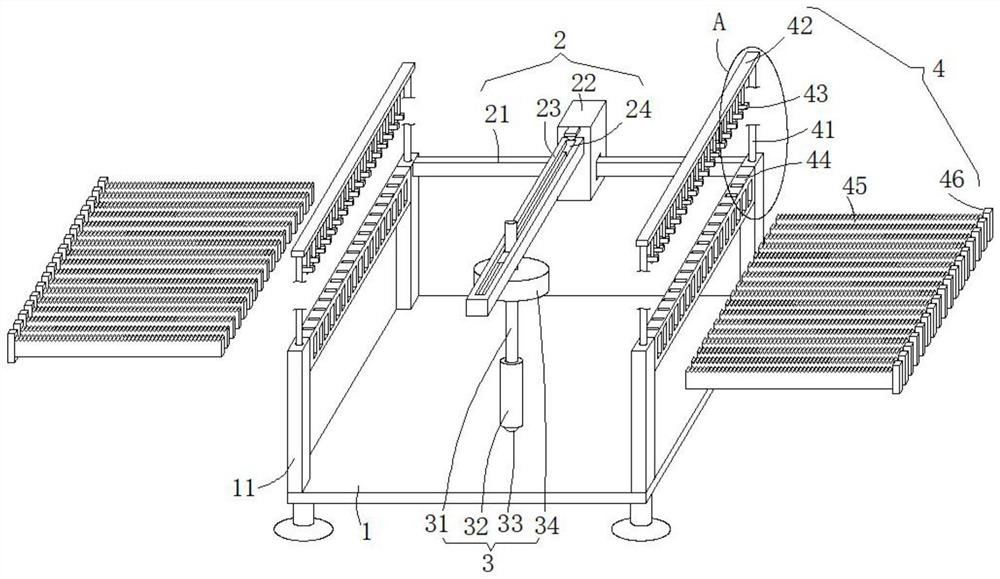
[0030] see Figure 1-3 , this embodiment provides a flexible cable lamination device and lamination method based on the Internet of Things, including a base 1, an adjustment mechanism 2 and a lamination mechanism 3, and the four corners of the upper end of the base 1 are vertically fixed with support columns 11. The adjustment mechanism 2 includes a crossbeam 21, and the axial ends of the crossbeam 21 are fixedly connected to the top positions of the two rear support columns 11 opposite to the side walls. The adjustment mechanism 2 adjusts the position of the fitting mechanism 3 to achieve the purpose of precisely fitting the flexible circuit board.

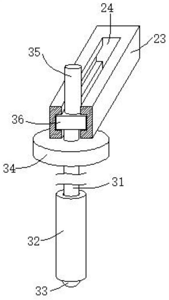
[0031] An adjustment seat 22 is slid on the crossbeam 21, and the top position of the front end of the adjustment seat 22 is hinged with an adjustment hoisting plate 23. The adjustment seat 22 can drive the adjustment hoisting plate 23 to freely adjust its position along the horizontal direction of the beam 21. The hinge with th...

Embodiment 2

[0038] see Figure 1-3 , made further improvement on the basis of embodiment 1:

[0039] In order to adjust the position of the fitting mechanism 3 with bare hands, a handle 35 that slides through the opening above the adjustment hole 24 is vertically fixed on the upper end of the rectangular slider 36. Holding the handle 35 with bare hands is convenient for applying force, and the rectangular slider can be slid along the adjustment hole 24. The block 36 uses the freely sliding rectangular slider 36 to drive the whole fitting mechanism 3 to slide and adjust the fitting position.

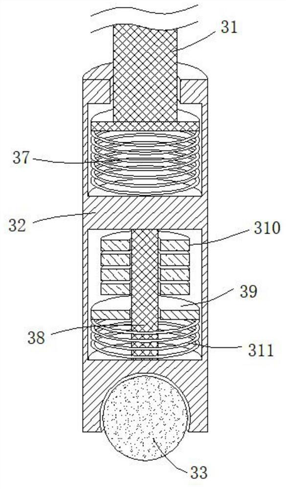
[0040] In order to improve the compactness of the iron pressing ball 33 when rolling and bonding, a buffer cavity located above the iron pressing ball 33 is provided inside the hoisting column 32. A slide bar 38 is fixedly installed, and the outer wall of the slide bar 38 is slidingly sleeved with a support plate 39 that can slide up and down according to the interior of the buffer cavity. The suppo...

Embodiment 3

[0044] see figure 1 and Figure 4 , made further improvement on the basis of embodiment 2:

[0045] The bonding mechanism 3 can be adjusted at any position on the upper end of the base 1, and it is impossible to carry out the rolling bonding operation according to the specific wiring position of the flexible circuit board. The guide plate 34 with the lower opening is provided with a guide mechanism 4 that can be used to limit the running track of the guide plate 34 between the two support columns 11 distributed front and back, and the guide mechanism 4 located on both sides of the guide plate 34 is used to limit the operation of the guide plate 34 track, so as to determine the position of the bonding mechanism 3 according to the wiring track of the flexible circuit board, so as to facilitate the precise rolling and bonding operation, and it is not easy to deviate.

[0046] The guide mechanism 4 includes an installation backing plate 44, and the front and rear ends of the ins...


PUM


Abstract

The invention discloses a flexible flat cable fitting device and fitting method based on the Internet of Things, which relate to the technical field of flexible flat cable fitting. The flexible flat cable fitting device comprises a base, an adjusting mechanism and a fitting mechanism, the adjusting mechanism comprises a cross beam, the two axial ends of the cross beam are fixedly connected with the top ends of the opposite side walls of two supporting stand columns on the rear side respectively, and an adjusting seat is slidably arranged on the cross beam; an adjusting hoisting plate is hinged to the top of the front end of the adjusting seat, the attaching mechanism comprises a rectangular sliding block and a hoisting column, an inverted-T-shaped hoisting rod penetrating through an opening in the lower portion of the adjusting hole in a sliding mode is fixedly arranged at the bottom end of the rectangular sliding block, and an inverted-T-shaped sliding groove connected with the inverted-T-shaped hoisting rod in a sliding and inserted mode is formed in the upper end of the hoisting column; and an iron pressing ball is rotationally embedded in the bottom end of the hoisting column. The fitting mechanism is used for rolling the flexible circuit board, so that the circuit can be fit and fixed, and the guide mechanism is arranged to freely arrange the fit running track, so that the flexible circuit board is quickly fixed and fit and is not easy to deviate, and the wiring efficiency is improved.

Description

technical field [0001] The invention relates to the technical field of flexible cable bonding, in particular to a flexible cable bonding device and a bonding method based on the Internet of Things. Background technique [0002] Flexible cable is a kind of data cable made of PET insulating material and extremely thin tinned flat copper wire. It is mainly used in the connection between the board end and the board end. , has been widely used in many related electrical products, precisely because of its soft texture, it is not easy to arrange and fix fit during installation, it is easy to deviate, and affects the normal wiring requirements, so here is a flexible row based on the Internet of Things A wire bonding device and a bonding method are provided so as to solve the above-mentioned problems. Contents of the invention [0003] The purpose of the present invention is to provide a flexible cable lamination device and lamination method based on the Internet of Things, so as ...

Claims


Application Information

Patent Timeline
Patent Type & Authority Applications(China)
IPC IPC(8): H05K3/30
CPCH05K3/305
Inventor 吴亚威
Owner 南京秉昱科技有限公司
Why Eureka
Try Eureka