Honeycomb-shaped cupping equipment

A honeycomb and equipment technology, which is applied in the field of head massage and honeycomb cupping equipment, can solve the problems of not reaching the massage effect, difficult to fix the tank, difficult to control negative pressure, etc.

Pending Publication Date: 2022-03-01
全成线
View PDF0 Cites 0 Cited by
  • Summary
  • Abstract
  • Description
  • Claims
  • Application Information

AI Technical Summary

Problems solved by technology

The main reason is that the head is difficult to fix the tank and the head pain caused by the difficulty in controlling the negative pressure
[0003] Ordinary cupping has a fixed mouth area, and the force on the body surface is only on the edge of the mouth. Long-term use will cause unbearable pain, and it is not suitable to use pulse pressure massage. The inside of the cup will easily lose the seal and the massage effect will not be achieved

Method used


Image

  • Honeycomb-shaped cupping equipment
  • Honeycomb-shaped cupping equipment
  • Honeycomb-shaped cupping equipment

Examples


no. 1 example

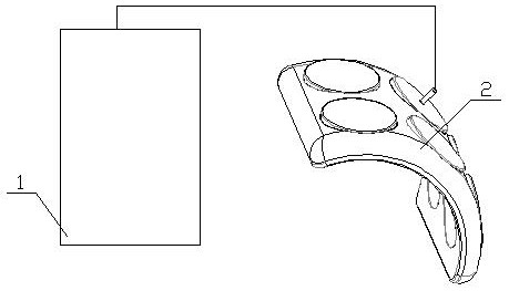
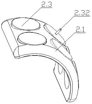
[0033] As shown in 1-5, the present invention includes a negative pressure generating device 1, a honeycomb cupping device 2, and the honeycomb cupping device 2 includes a base body 2.1 and a tank body 2.3.

[0034] The base body 2.1 is made of elastic polymer material, so that the base body 2.1 can be deformed with the shape of the contact surface body surface when the negative pressure works, so that the honeycomb cupping device 2 can be tightly attached to the body surface, and the base body 2.1 is facing the body surface. One side can be designed as arc or plane structure.

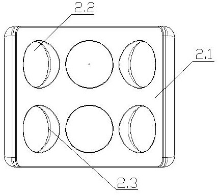
[0035] The base body 2.1 is provided with a plurality of tank holes 2.2 arranged in a honeycomb shape. The number of tank bodies 2.3 is the same as that of the tank holes 2.2, and the open ends are respectively sleeved in the tank holes 2.2. The tank body 2.3 is a structure with one end open and one end closed. Part or all of the inner cavities of the tank body 2.3 set on the base body 2.1 are communic...

no. 2 example

[0052] The difference between the second embodiment and the first embodiment is that the base structure of the honeycomb cupping device 2 is as follows: Figure 10 , 11 As shown, the base 2.1 of the honeycomb cupping device 2 of this embodiment includes a plurality of annular tank seats 10, the wall thickness of the annular tank seat 10 is 1.8-2.5mm, and the central hole of the annular tank seat 10 is used as the tank hole 13. , the tank hole 13 is used to assemble the tank, the annular tank seat 10 is connected as a whole by the flexible pad 11, the thickness of the flexible pad 11 is 0.8-1.2mm, the annular tank seat 10 and the flexible pad 11 are made of elastic Made of polymer material.

[0053] The side of the flexible pad 10 and the annular tank seat 11 in contact with the body surface is flush, and the side of the adjacent pad tank seat 10 facing the body surface and the flexible pad 11 are provided with a connection connecting the adjacent tank holes 13. Strip groove ...


PUM


Abstract

The invention discloses honeycomb-shaped cupping equipment, and relates to the technical field of medical treatment equipment. Comprising a negative pressure generating device, a cupping device attached to the body surface for use and a sealing assembly used for forming sealing between the cupping device and the body surface, the cupping device is in surface contact with the body surface, the negative pressure generating device is connected with the cupping device through an air channel, and the negative pressure generating device is used for vacuumizing the cupping device. According to the honeycomb-shaped cupping equipment provided by the invention, the cupping device is in surface contact with the body surface, and the surface contact can disperse pressure in a negative pressure state and reduce pain caused by compression.

Description

technical field [0001] The invention relates to the technical field of medical treatment equipment, in particular to a honeycomb cupping equipment, which is used for body surface massage, especially head massage. Background technique [0002] There are many kinds of negative pressure massage devices, but there are very few equipments for head negative pressure massage, especially pulse pressure massage. The main reason is the head pain caused by the difficulty in fixing the tank and the difficulty in controlling the negative pressure. [0003] Ordinary cupping has a fixed area of ​​the mouth of the can, and the force on the body surface is only on the edge of the mouth of the can. Long-term use will cause unbearable pain, and it is not suitable to use pulse pressure massage. SUMMARY OF THE INVENTION [0004] The purpose of the present invention is to provide a honeycomb cupping device, which can effectively solve the problems in the background art. [0005] The technical...

Claims


Application Information

Patent Timeline
Patent Type & Authority Applications(China)
IPC IPC(8): A61M1/08A61H9/00
CPCA61M1/08A61H9/0057A61H2205/02
Inventor 全成线
Owner 全成线
Why Eureka
Try Eureka