Pipe detection device

A detection device and pipe technology, applied in measurement devices, mechanical measurement devices, and mechanical devices, etc., can solve the problems of inconvenience for manufacturers, low detection efficiency, high detection cost, etc., and achieve simple and clear operation, improve detection accuracy, and precision. high sex effect

Active Publication Date: 2022-03-08
李田光
View PDF47 Cites 2 Cited by
  • Summary
  • Abstract
  • Description
  • Claims
  • Application Information

AI Technical Summary

Problems solved by technology

[0003] After the pipe is produced, it is necessary to carry out a series of inspections on the pipe to avoid the flow of defective pipes into the market. The detection of pipes is inseparable from the detection device. The existing pipe detection device can only detect one part of the pipe. When it is necessary to detect multiple parts of the pipe, multiple different detection devices need to be used for detection, the detection efficiency is low, and the detection cost is high, which is greatly inconvenient for manufacturers to use

Method used


Image

  • Pipe detection device
  • Pipe detection device
  • Pipe detection device

Examples


Embodiment 1

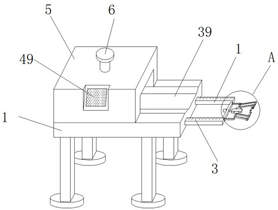
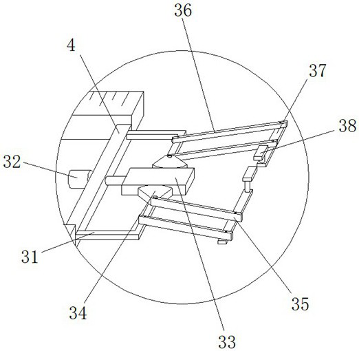
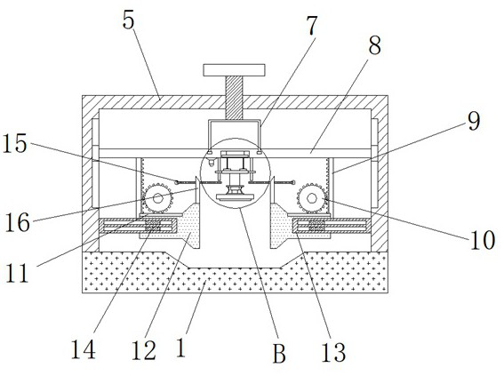
[0033] Such as Figure 1-5As shown, the pipe detection device according to the embodiment of the present invention includes a base 1, one side of the base 1 is provided with a symmetrically arranged slide bar 2, and the top of the slide bar 2 is provided with a scale 3, and the two groups of A connecting plate-4 is provided between the slide bars 2, a limit mechanism is provided on one side of the connecting plate-4, a box body 5 is provided on one side at the top of the base 1, and a box body 5 is provided on the top end of the box body 5. There is a threaded rod 6 extending to its inside, the bottom end of the threaded rod 6 is provided with a movable cylinder 7, and the bottom end of the movable cylinder 7 is provided with a connecting plate 2 8 that is movably connected with it, and the connecting plate 2 8 The bottom end is provided with locking mechanism, and described casing 5 is provided with the scale bar 15 that is arranged symmetrically, and one end of described sca...

Embodiment 2

[0035] Such as Figure 1-5 As shown, according to the pipe detection device according to the embodiment of the present invention, the locking mechanism includes a symmetrically arranged rack one 9 located at the bottom end of the connecting plate two 8, and one of the two sets of racks one 9 close to each other Each side is provided with a gear one 10 meshed with it, the bottom end of the gear one 10 is provided with a rack two 11 meshed with it, and the bottom end of the rack two 11 is provided with a gear connected to the measuring rod 16. Extrusion block 12, a pair of limit strips 13 are provided on both sides of the box body 5, and protrusions that are symmetrically arranged and slidably connected with the limit strips 13 are provided on both sides of the extrusion block 12. Block one 14, the specific structure of the locking mechanism can play a fixing effect on the pipe, ensure the stability and firmness of the pipe, and improve the measurement accuracy of the pipe.

Embodiment 3

[0037] Such as Figure 1-5 As shown, according to the pipe inspection device according to the embodiment of the present invention, the pressure measurement mechanism includes a symmetrically arranged limit rod 21 located at the bottom end of the connecting plate 2 8, and the limit rod 21 is sleeved with a matching The sliding sleeve of the two groups of sliding sleeves is provided with a fixed plate 22, and the top of the fixed plate 22 and the bottom end of one of the transmission wheels 19 are provided with some evenly distributed projections 23. The second bump 23 is provided with universal balls 24 that are movably connected with it. The universal balls 24 of the upper and lower groups are all connected by connecting rods 25. The bottom end of the fixed plate 22 is provided with a fixed column 26. The bottom end of the fixed column 26 is provided with a pair of vertically distributed reinforcement plates 27, and the two groups of reinforcement plates 27 are connected by sy...


PUM


Abstract

The invention discloses a pipe detection device which comprises a base, sliding rods are symmetrically arranged on one side of the base, graduated scales are arranged at the top ends of the sliding rods, a first connecting plate is arranged between the two sets of sliding rods, a limiting mechanism is arranged on one side of the first connecting plate, and a box body is arranged on one side of the top end of the base. A threaded rod extending into the box body is arranged at the top end of the box body, a movable cylinder is arranged at the bottom end of the threaded rod, a second connecting plate movably connected with the movable cylinder is arranged at the bottom end of the movable cylinder, a locking mechanism is arranged at the bottom end of the second connecting plate, and scale rods are symmetrically arranged in the box body. The pipe length measuring device has the advantages that the sliding rod is moved forwards and matched with the limiting mechanism to enable the two sets of limiting check blocks to be close to each other in an arc shape and to be tightly connected, when the sliding rod is moved reversely, the limiting check blocks can make contact with one end of a pipe, meanwhile, the graduated scale is arranged at the top end of the sliding rod and matched with scale teeth to measure the length of the pipe, operation is easy and clear, and accuracy is high.

Description

technical field [0001] The invention relates to the technical field of pipe detection, in particular to a pipe detection device. Background technique [0002] Pipes are necessary materials for construction projects, and such pipes are often used in construction projects, power plants, and chemical plants. Different pipe fittings use different pipe materials, and pipe materials for different purposes have corresponding implementation standards. The quality of pipe materials directly determines the quality of pipe fittings. Common pipes are: PPR pipe, PVC pipe, UPVC pipe, copper pipe, steel pipe, fiber pipe, composite pipe, galvanized pipe, hose, reducer, water pipe, etc. [0003] After the pipe is produced, it is necessary to carry out a series of inspections on the pipe to avoid the flow of defective pipes into the market. The detection of pipes is inseparable from the detection device. The existing pipe detection device can only detect one part of the pipe. When it is nec...

Claims


Application Information

Patent Timeline
Patent Type & Authority Applications(China)
IPC IPC(8): G01N3/12G01N3/02G01B5/02G01B5/08
CPCG01N3/12G01N3/02G01B5/02G01B5/08G01N2203/0019G01N2203/0048
Inventor 李田光
Owner 李田光
Why Eureka
Try Eureka