Method and device for detecting lamp tube, electronic equipment and storage medium
A technology for storage media and lamps, applied in the field of automation, can solve problems such as the inability to determine the intensity and irradiation requirements of lamps
- Summary
- Abstract
- Description
- Claims
- Application Information
AI Technical Summary
Problems solved by technology
Method used
Image

Examples
example 1
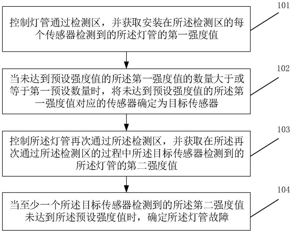
[0071] Example 1, assuming that seven sensors are set up in the detection area, which are used to detect seven different areas of the lamp tube, for the first sensor, when the lamp tube passes through the detection area, the first sensor detects multiple intensities value, take the largest intensity value as the first intensity value of the first sensor; each sensor determines the detected first intensity value according to the above method.
[0072] Step 102, when the number of the first intensity values that do not reach the preset intensity value is greater than or equal to the first preset number, determine the sensor corresponding to the first intensity value that does not reach the preset intensity value as the target sensor .
[0073] Specifically, after obtaining the first intensity value representing the irradiation intensity of the lamp according to step 101, it is determined whether each first intensity value is greater than or equal to the preset intensity value,...
example 2
[0074] Example 2, based on the solution of Example 1 above, it is assumed that the first intensity values of the seven sensors are: 2, 3, 3, 3, 4, 2, and 2, respectively. Suppose the preset intensity value is 3; the first preset number is 3; wherein, the unit of intensity value is v / cm 2 .
[0075] Then, the first intensity values of the first sensor, the sixth sensor and the seventh sensor are all smaller than the preset intensity value; then the number of the first intensity values smaller than the preset intensity value is 3, which is equal to the first preset number 3, and the The first sensor, the sixth sensor and the seventh sensor are determined as target sensors.
[0076] Step 103: Control the light tube to pass through the detection area again, and acquire a second intensity value of the light tube detected by the target sensor during the process of passing through the detection area again.
[0077] Specifically, after the target sensor is determined according...
example 3
[0086] Example 3, based on the solution of Example 1 above, it is assumed that the first intensity values of the seven sensors are: 3, 3, 3, 3, 4, 4, and 2, respectively. Suppose the preset intensity value is 3; the first preset number is 3.
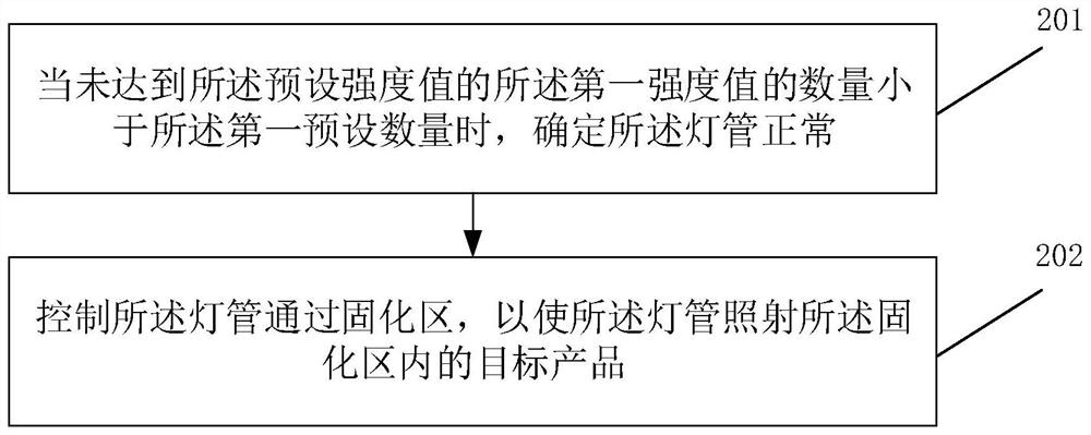
[0087] Then, only the first intensity value 2 of the seventh sensor is less than the preset intensity value 3; then the number of first intensity values less than the preset intensity value is 1, which is less than the first preset number 3, and it is considered that the first intensity value of the seventh sensor The intensity value may have a certain deviation due to problems such as communication delay, poor communication, and inaccurate detection by the first sensor, and then it is determined that the current lamp is normal.
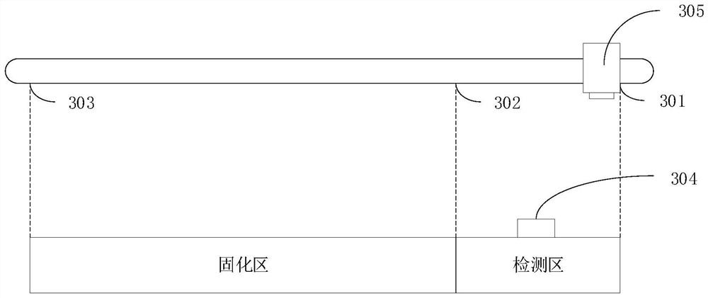
[0088] Step 202 , controlling the lamp to pass through the curing area, so that the lamp irradiates the target product in the curing area; the lamp faces the curing area.
[0089] Specifically, when it is de...
PUM
 Abstract
Description
Claims
Application Information
 - R&D Engineer
- R&D Manager
- IP Professional
- Industry Leading Data Capabilities
- Powerful AI technology
- Patent DNA Extraction
Browse by: Latest US Patents, China's latest patents, Technical Efficacy Thesaurus, Application Domain, Technology Topic.
© 2024 PatSnap. All rights reserved.Legal|Privacy policy|Modern Slavery Act Transparency Statement|Sitemap