
Cutter block switching structure of stamping die

A punching die and cutter block technology, which is applied in the field of cutter block switching structure, can solve the problems of inability to limit the longitudinal position and the slippage is not stable enough, and achieve the effects of smooth movement, good punching work, and stable switching.

Inactive Publication Date: 2022-03-11
FUZHEN TECH RES ANHUI
View PDF7 Cites 1 Cited by
  • Summary
  • Abstract
  • Description
  • Claims
  • Application Information

AI Technical Summary

Problems solved by technology

However, in this patent, the knife block is pushed up and down by the slider in a longitudinal sliding groove. Using a sliding slope to slide is not stable enough, and because it slides in the sliding groove, the vertical position cannot be limited, and a guide mechanism is required. Guided and top-limited switching mechanism

Method used


Image

  • Cutter block switching structure of stamping die
  • Cutter block switching structure of stamping die
  • Cutter block switching structure of stamping die

Examples


Embodiment Construction

[0020] In order to deepen the understanding of the present invention, the present invention will be further described below in conjunction with the examples, which are only used to explain the present invention, and do not constitute a limitation to the protection scope of the present invention.

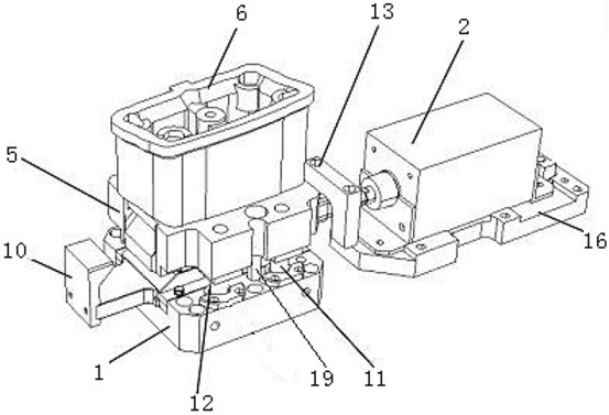
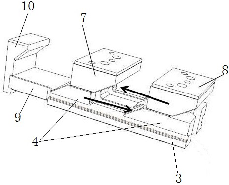
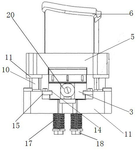
[0021] Such as Figure 1-4 As shown, this embodiment provides a knife block switching structure of a stamping die, including a base 1 and a cylinder 2 on the right side of the base 1, the bottom of the cylinder 2 is fixed on the mold through the cylinder fixing seat 16, and the top of the base 1 is set There is a driving knife 3 that moves left and right, and the cylinder 2 is connected to the driving knife 3 through a connecting rod 20. The top of the driving knife 3 is two left and right knife blocks 4 with a gap in the middle; a mounting plate 5 is arranged above the driving knife 3, The bottom edge of the mounting plate 5 is movably arranged on the base 1 through a longitudinal g...


PUM


Abstract

According to the cutter block switching structure of the stamping die, the driving slotting cutter is driven by the air cylinder to be pulled rightwards so that the two slotting cutter blocks can move rightwards, the driven slotting cutter and the match grinding base plate move leftwards relatively to fall onto an extension plate on the left side of the slotting cutter block on the left side and a gap between the left slotting cutter block and the right slotting cutter block correspondingly, and therefore the mounting plate moves downwards through the guide mechanism; a safety limiting screw penetrating through the mounting plate and the base is used for limiting the top end of the mounting plate, so that the position of the top end of the cutter block is limited, a slotting tool is cooperatively driven to limit the bottom end of the cutter block, the position of the cutter block is fixed, and stamping work is better conducted; and the switching is more stable.

Description

technical field [0001] The invention relates to the field of stamping dies, in particular to a knife block switching structure of the stamping die. Background technique [0002] In recent years, with the complex and changeable shapes of automobile panels, the design and manufacturing costs of various molds have remained high. Only by adopting molds with new mechanisms and new processes can automobile mold manufacturers effectively reduce development costs and accelerate market growth. competition rate. Now for the sunroof and non-sunroof, car panels with and without fuel fillers in the same model, the OEM usually only develops one pair of molds, and requires it to have two production capacities at the same time. switch between the forms. The one-sequence mold needs to have two states. Although the process is compressed, the single-process mold takes on more content. Under this concept, the design space of the mold is becoming more and more compact. When the traditional mol...

Claims


Application Information

Patent Timeline
Patent Type & Authority Applications(China)
IPC IPC(8): B21D37/02B21D37/08B21D53/88
CPCB21D37/02B21D37/08B21D53/88
Inventor 李龙杨天鑫焦克成
Owner FUZHEN TECH RES ANHUI
Learn More