Method for operating ultrasonic flowmeter and ultrasonic flowmeter

An ultrasonic flow and measuring instrument technology, which is applied in the measurement of flow/mass flow, fluid velocity measurement, liquid/fluid solid measurement, etc., can solve the problems of measurement accuracy influence, flow measurement repetition rate limitation, etc.

Pending Publication Date: 2022-03-11
KRONE GMBH
View PDF3 Cites 2 Cited by
  • Summary
  • Abstract
  • Description
  • Claims
  • Application Information

AI Technical Summary

Problems solved by technology

[0006] However, this method has the disadvantage that the repetition rate of the flow measurement is limited
It can also happen that the flow velocity changes during the measurement interval, i.e. in the time between emission and reception of the measurement signal, which likewise has a negative effect on the measurement accuracy

Method used


Image

  • Method for operating ultrasonic flowmeter and ultrasonic flowmeter
  • Method for operating ultrasonic flowmeter and ultrasonic flowmeter
  • Method for operating ultrasonic flowmeter and ultrasonic flowmeter

Examples


Embodiment Construction

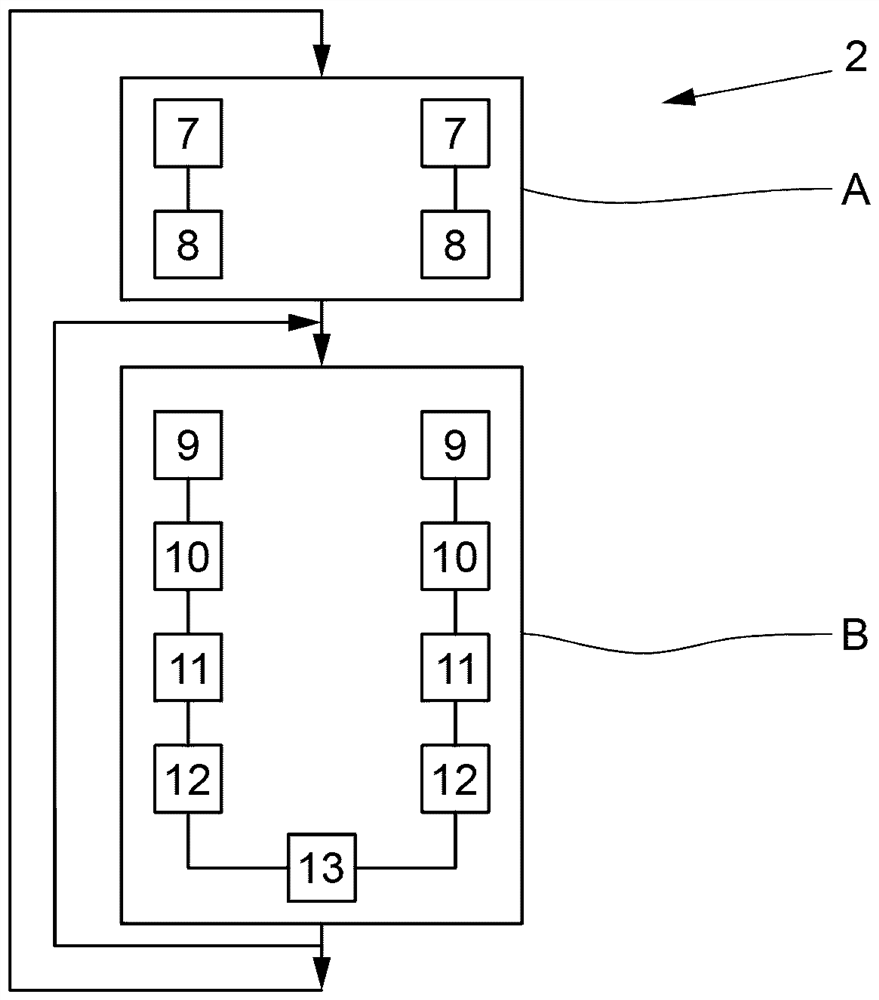
[0084] figure 1 An exemplary embodiment of an ultrasonic flowmeter 1 is shown, wherein the ultrasonic flowmeter 1 has an ultrasonic transducer pair consisting of a first ultrasonic transducer 3 and a second ultrasonic transducer 4 . Ultrasonic transducers 3 and 4 are arranged offset to one another in the flow direction on measuring tube 5 . In the illustrated embodiment, the direction of flow is indicated by arrows.

[0085] The two ultrasonic transducers 3 and 4 are designed not only as a transmitting unit but also as a receiving unit. In operation, the second ultrasonic transducer 4 receives the first measurement signal emitted by the first ultrasonic transducer 3 and the first ultrasonic transducer 3 receives the second measurement signal emitted by the second ultrasonic transducer 4 . Thus, the result is that during operation a measurement signal passes in the direction of flow (verlaufen) and a measurement signal passes opposite to the direction of flow. From the trans...


PUM


Abstract

The invention relates to a method for operating an ultrasonic flowmeter, comprising: at least one first ultrasonic transducer configured as a transmitting unit and a receiving unit; a measuring tube through which the medium flows during operation; and a control and evaluation unit for actuating the at least first ultrasonic transducer and for determining a flow rate or flow rate of the medium, the method comprising: detecting at least one first ringing signal of the first ultrasonic transducer and determining a first ringing interference suppression signal on the basis of the detected at least one first ringing signal; transmitting the first measurement signal into the medium by means of a first ultrasonic transducer, wherein a first ringing measurement signal is generated in the first ultrasonic transducer; receiving the measurement signal as a first reception signal by the first ultrasonic transducer, superimposing the first reception signal and the first ringing measurement signal into a first superimposed signal, and determining a first correction signal by subtracting the first ringing interference suppression signal from the first superimposed signal; and determining a flow rate or flow rate based on the first correction signal.

Description

technical field [0001] The invention is based on a method for operating an ultrasonic flowmeter, wherein the ultrasonic flowmeter has: at least one first ultrasonic transducer, wherein the first ultrasonic transducer is configured as a transmitting unit and a receiving unit; and a measuring tube (Messrohr ), wherein during operation a medium flows through the measuring tube; and a control and evaluation unit for actuating at least the first ultrasonic transducer and for determining the flow velocity or flow rate of the medium. [0002] The invention also relates to an ultrasonic flow measuring device having at least one first ultrasonic transducer, wherein the first ultrasonic transducer is designed as a transmitting unit and a receiving unit and having a measuring A tube through which a medium flows during operation, and the ultrasonic flowmeter has a control and evaluation unit for actuating at least a first ultrasonic transducer and for determining the flow velocity of the ...

Claims


Application Information

Patent Timeline
Patent Type & Authority Applications(China)
IPC IPC(8): G01F1/667G01P5/24
CPCG01F1/667G01P5/245G01F1/66G01F1/662
Inventor A·赫伊泽尔
Owner KRONE GMBH
Why Eureka
Try Eureka