Geotechnical engineering investigation drilling machine soil sampler and soil sampling method

A technology of geotechnical engineering and soil fetching device, which is applied in the direction of sampling devices, etc., can solve the problems of affecting construction progress, destroying soil samples, and slow speed, and achieves the effects of convenient installation and disassembly, light soil fetching structure, and high sampling success rate

Pending Publication Date: 2022-03-15
YULIN NORMAL UNIVERSITY
0 Cites 0 Cited by

AI-Extracted Technical Summary

Problems solved by technology

[0002] With the rapid development of science and technology, geotechnical engineering investigation is playing an increasingly important role in engineering construction. In geotechnical engineering investigation, it is often ne...

Method used

In the present embodiment, interface seat 4 is provided with threaded interface 9, and the bottom end of main rod 5 is provided with the first screw rod 10 that is connected with interface seat 4, and main rod 5 is con...

Abstract

The invention discloses a geotechnical engineering investigation drilling machine soil sampler which comprises a soil sampler body, the soil sampler body comprises a gasket and a connector seat connected with a drilling machine underframe, a vertically-arranged main rod is installed on the connector seat, a rotating seat is rotationally arranged at the top of the main rod, a handle is arranged on one side of the rotating seat, and the gasket is arranged on the handle. And a soil jacking rod is arranged on one side of the rotating seat. The invention further discloses a soil sampling method of the geotechnical engineering investigation drilling machine. The geotechnical engineering investigation drilling machine soil sampler and the soil sampling method belong to the technical field of geotechnical engineering investigation detection equipment, soil sampling is carried out through the soil sampler, disturbance to a soil sample is small, and the original shape of the soil sample can be fully maintained; the device is labor-saving, time-saving, efficient and high in sampling success rate; the soil sampling structure is light, energy-saving, environment-friendly and convenient to mount and dismount.

Application Domain

Withdrawing sample devices

Technology Topic

Soil scienceGeotechnical engineering +2

Image

  • Geotechnical engineering investigation drilling machine soil sampler and soil sampling method
  • Geotechnical engineering investigation drilling machine soil sampler and soil sampling method
  • Geotechnical engineering investigation drilling machine soil sampler and soil sampling method

Examples

  • Experimental program(1)

Example Embodiment

[0026] The specific embodiments of the present invention will be described in detail below with reference to the accompanying drawings, but it should be understood that the protection scope of the present invention is not limited by the specific embodiments.
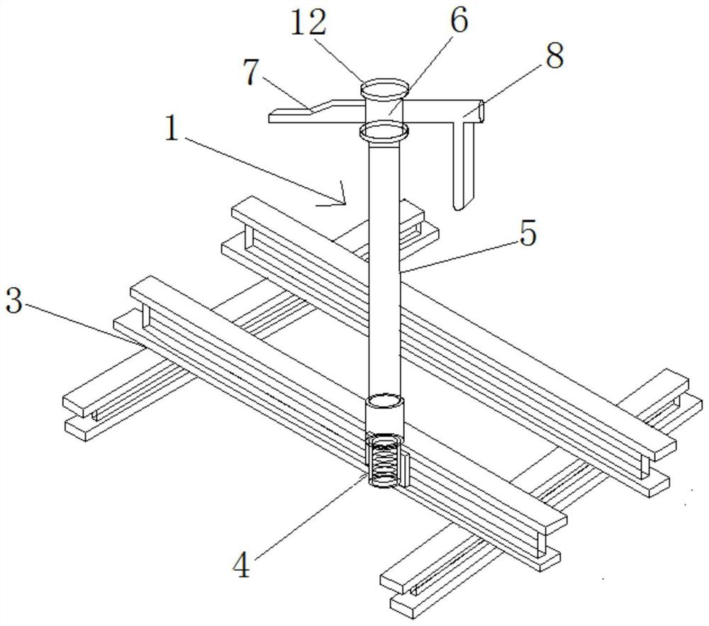
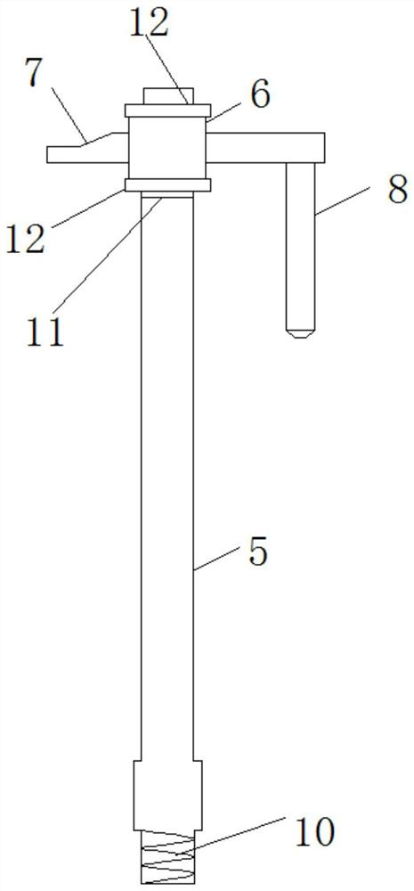
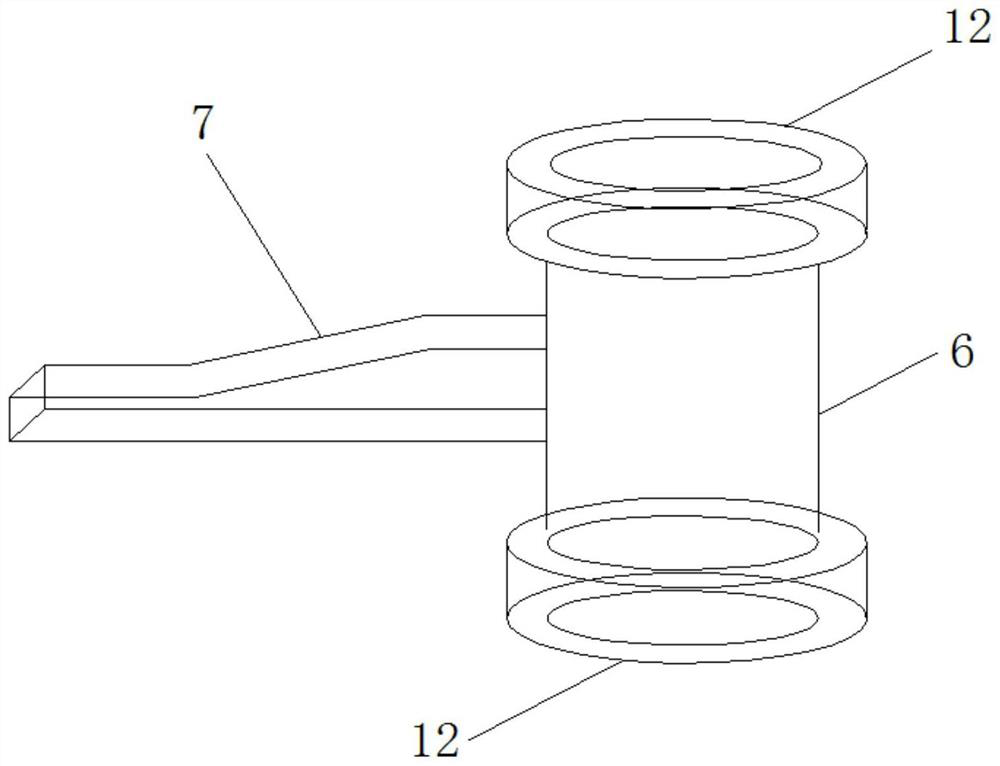
[0027] The specific embodiment of the present invention is as follows: Figure 1-6 As shown, a soil extractor for a geotechnical engineering survey drilling rig includes a soil extractor body 1, and the soil extractor body 1 includes a gasket 2 and an interface seat 4 connected with the drilling rig chassis 3, and the interface seat 4 is installed with a vertically arranged main Rod 5, the top of the main rod 5 is rotated with a rotating seat 6, one side of the rotating seat 6 is provided with a handle 7, and one side of the rotating seat 6 is provided with a jacking rod 8.
[0028] In the earth borrower of this geotechnical engineering survey drilling rig, the drill pipe of the drill rig is a cylindrical structure, the gasket 2 is matched with the inner hole of the drill pipe, the interface seat 4 is fixed on the drilling rig chassis 3 by welding, and the main rod of the earth borrower body 1 5 is vertically installed on the interface seat 4 through the thread, the rotating seat 6 is sleeved on the top of the main rod 5, the handle 7 and the top soil rod 8 are installed on one side of the rotating seat 6, the rotating seat 6 can be rotated through the handle 7, and the rotating seat 6 can be rotated. The base 6 is a cylindrical structure, so that the top soil rod 8 on the rotary base 6 is in contact with the soil sample in the inner hole of the drill rod, and the drill rod of the drilling rig is lifted up, and the top soil rod 8 can be used to lift the drilling rig's The soil sample in the drill pipe is extruded downward to complete the sampling. The soil sample is in the shape of a long strip, and the soil sample is not easily damaged, which is convenient for the transportation and preservation of the soil sample, and can also prevent the interior of the soil sample from being oxidized.
[0029] Therefore, the soil sampling through this soil borrower has little disturbance to the soil sample and can fully maintain the original state of the soil sample; the use of this device for sampling is labor-saving, time-saving, efficient, and has a high sampling success rate; the soil sampling structure is light, energy-saving and environmentally friendly, and the installation and Easy to disassemble.
[0030] The gasket 2 is used to place the top of the soil sample in the inner hole of the drill pipe. The gasket 2 is adapted to the hole wall of the inner hole of the drill pipe. By squeezing the gasket 2 through the top soil rod 8, the soil sample in the drill pipe can be squeezed. out to prevent the soil sample from sticking to the hole wall of the inner hole of the drill pipe.
[0031] In this embodiment, the interface seat 4 is provided with a threaded interface 9, the bottom end of the main rod 5 is provided with a first screw 10 connected to the interface seat 4, and the main rod 5 is connected with the threaded interface 9 through the first screw 10, so that The earth extractor body 1 can be quickly installed on the bottom frame 3 of the drilling rig, with convenient installation and simple operation.
[0032] In the present embodiment, the top of the main rod 5 is provided with a second screw 11 , the rotating base 6 is sleeved on the second screw 11 , and the second screw 11 is provided with limiters adapted to the upper and lower end surfaces of the rotating base 6 . The nut 12 and the limit nut 12 can limit the rotating seat 6 to prevent the rotating seat 6 from sliding up and down, so as to ensure that the top soil rod 8 can extrude the soil sample in the drill pipe downward.
[0033] In this embodiment, the top of the first screw 10 is provided with an insertion hole, the main rod 5 is inserted in the insertion hole, and the main rod 5 is fixed in the insertion hole by welding.
[0034] In this embodiment, the jacking rod 8 includes a straight rod section 13 connected to the rotating base 6 and a vertical section 14 disposed at the outer end of the straight rod section 13. The entire jacking rod 8 is in the shape of a The vertical section 14 can extend into the vertically arranged drill pipe inner hole.
[0035] In this embodiment, the straight rod section 13 is provided with a sleeve hole 15, and the handle 7 is inserted into the sleeve hole 15. Tightening the screw can quickly fix the handle 7 and the straight rod section 13 of the jacking rod 8 .
[0036] A soil borrowing method using an earth borrower of a geotechnical engineering survey drilling rig, the method comprising the following steps: fixing the earth borrower body 1 on the drilling rig chassis 3 through an interface seat 4, and controlling the drill pipe of the drilling rig to be close to the earth borrower body 1, Place the gasket 2 on the top of the inner hole of the drill pipe, then turn the rotary seat 6 through the handle 7 to make the bottom of the jacking rod 8 align with the gasket 2 at the top of the inner hole of the drill pipe, and then control the drill pipe of the drilling rig to lift up, and the top The soil rod 8 extrudes the soil sample in the inner hole of the drill rod downward.
[0037] The interface seat 4 is provided with a threaded interface 9, the bottom end of the main rod 5 is provided with a first screw 10 connected to the interface seat 4; the top of the main rod 5 is provided with a second screw 11, and the rotating seat 6 is sleeved on the second screw 11 , the second screw 11 is provided with a limit nut 12 which is adapted to the upper and lower end surfaces of the rotating seat 6 .
[0038] The jacking rod 8 includes a straight rod section 13 connected with the rotating base 6 and a vertical section 14 arranged at the outer end of the straight rod section 13 .
[0039] The straight rod section 13 is provided with a sleeve hole 15 , and the handle 7 is inserted into the sleeve hole 15 .
[0040] When taking soil: First, adjust the position of the drill pipe of the drill rig so that the drill pipe of the drill rig is close to the body 1 of the soil extractor, put the gasket on the soil sample in the inner hole of the drill pipe, rotate the handle 7 and adjust the position of the drill pipe of the drill rig so that the The top soil rod 8 can enter the drill pipe of the drilling rig and withstand the soil sample; finally, lift the drill rod of the drilling rig, and the top soil rod 8 pushes out the soil sample in the drill rod to complete the sampling.
[0041] The above are only the preferred embodiments of the present invention, and it should be pointed out that for those skilled in the art, without departing from the structure of the present invention, several modifications and improvements can be made, which will not affect the effect and effect of the present invention. Utility of Patents.

PUM

no PUM

Description & Claims & Application Information

We can also present the details of the Description, Claims and Application information to help users get a comprehensive understanding of the technical details of the patent, such as background art, summary of invention, brief description of drawings, description of embodiments, and other original content. On the other hand, users can also determine the specific scope of protection of the technology through the list of claims; as well as understand the changes in the life cycle of the technology with the presentation of the patent timeline. Login to view more.

Similar technology patents

Metal die tool

InactiveCN106424566AEasy to install and removeImprove casting efficiency
Owner:TIANJIN LONGHE STEEL ALTERED METAL PROD CO LTD

Efficient portable river sediment sampling apparatus

InactiveCN108195623AReduce the chance of tiltingImprove sampling success rate
Owner:浙江亿太诺气动科技有限公司

Drawer backboard connecting device

InactiveCN101606787AEasy to install and removeEliminate shear force
Owner:李绍汉

Mail reminder

InactiveCN103713985AThe screws are fixed firmlyEasy to install and remove
Owner:谢虹

Classification and recommendation of technical efficacy words

  • Improve sampling success rate

Efficient portable river sediment sampling apparatus

InactiveCN108195623AReduce the chance of tiltingImprove sampling success rate
Owner:浙江亿太诺气动科技有限公司
Why Eureka
Try Eureka