
Emergency help seeking device for smart scenic spot

An emergency rescue and scenic spot technology, applied in signal devices, visible signal devices, data processing applications, etc., can solve the problems of inability to quickly remove, difficult to search and rescue, and inability to locate and locate tourists with communication equipment. The effect of disassembly

Inactive Publication Date: 2022-03-18
TOURISM COLLEGE OF ZHEJIANG
View PDF0 Cites 0 Cited by
  • Summary
  • Abstract
  • Description
  • Claims
  • Application Information

AI Technical Summary

Problems solved by technology

[0004] In order to solve the above technical problems, an emergency rescue device for smart scenic spots is provided. This technical solution solves the problem that the existing scenic spot emergency rescue devices proposed in the above-mentioned background technology are relatively sparse in the scenic spot and cannot be used in combination with street lights, causing tourists to sleep at night. It is inconvenient to find a rescue device when lost, and the signal is weak in some scenic spots. Usually, search and rescue personnel are required to find lost tourists, and it is impossible to locate and find tourists through communication equipment, which makes search and rescue difficult and inefficient. Some lamps are usually fixed on the emergency rescue device in the scenic area, which cannot be quickly removed and used as hand-held lamps, which makes it difficult for tourists to find the exit at night

Method used


Image

  • Emergency help seeking device for smart scenic spot
  • Emergency help seeking device for smart scenic spot
  • Emergency help seeking device for smart scenic spot

Examples


Embodiment Construction

[0031]The following will clearly and completely describe the technical solutions in the embodiments of the present invention with reference to the accompanying drawings in the embodiments of the present invention. Obviously, the described embodiments are only some, not all, embodiments of the present invention. Based on the embodiments of the present invention, all other embodiments obtained by persons of ordinary skill in the art without making creative efforts belong to the protection scope of the present invention.

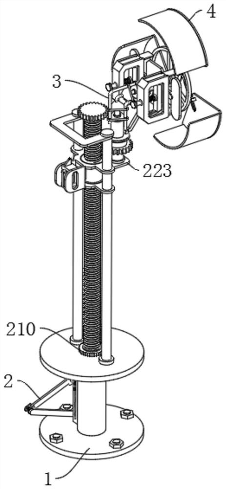
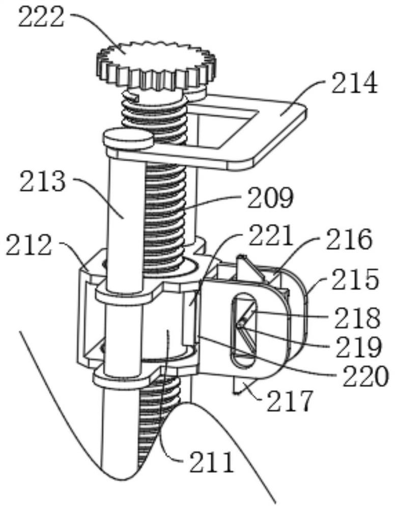
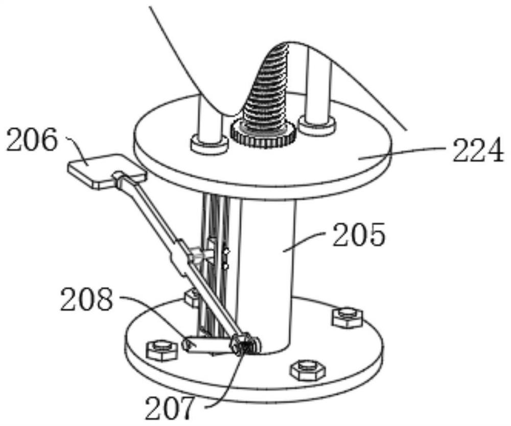
[0032] refer to figure 1 and figure 2 and image 3 and Figure 4 and Figure 5 As shown, an emergency rescue device for a smart scenic spot includes a base mounting plate 1, a driving mechanism 2 is arranged on the upper end of the base mounting plate 1, a rotating easy-to-detach mechanism 3 is arranged on the right end of the driving mechanism 2, and a rotating easy-to-detach mechanism 3 is arranged on the right end. The closing mechanism 4, the driving m...


PUM


Abstract

A closing mechanism comprises a power ring and a triangular connecting rod, the right end of a short shaft rod is fixedly connected with the power ring, the triangular connecting rod is fixedly connected to the right end of a hollowed-out sliding groove plate, the triangular connecting rod is evenly and rotatably connected with a plurality of power sliding groove rods, and the left ends of the power sliding groove rods are slidably connected with sliding rods; the front end of the sliding rod is fixedly connected to the rear end of the power ring, a plane mounting frame is welded to the outer surface of one end of the power sliding groove rod, and an arc closing plate is fixedly connected to the front end of the plane mounting frame. A short shaft rod drives a power ring to rotate, the power ring drives a power sliding groove rod to rotate through a sliding rod, one end of the power sliding groove rod is positioned through a triangular connecting rod, when the sliding rod slides to the lower end of the power sliding groove rod, an arc closing plate is in an unfolded rotating state, and when the sliding rod slides at the middle end of the power sliding groove rod, the arc closing plate is in a semi-open rotating state. When the power ring continues to rotate in the same direction, the sliding rod slides to the upper end of the power sliding groove rod.

Description

technical field [0001] The invention relates to the field of smart scenic spots, in particular to an emergency rescue device for smart scenic spots. Background technique [0002] Smart scenic spot refers to the comprehensive, thorough and timely perception of geographical objects, natural resources, tourist behavior, scenic spot staff's deeds, scenic spot infrastructure and service facilities through the intelligent network; it realizes visual management of tourists and scenic spot staff, Among them, there are few emergency rescue devices installed in some scenic spots, and it is impossible to accurately locate the lost tourists. [0003] The existing emergency rescue devices in scenic spots are relatively sparse and cannot be used in combination with street lights, causing tourists to find it inconvenient to find rescue devices when they get lost at night, and the signal in some scenic spots is weak, usually requiring search and rescue personnel to find lost tourists, unabl...

Claims


Application Information

Patent Timeline
IPC IPC(8): G08B21/02G08B5/38G06Q50/14
CPCG08B21/02G08B5/38G06Q50/14
Inventor 韦小良汪永旗范平徐慧慧詹兆宗
Owner TOURISM COLLEGE OF ZHEJIANG
Learn More