
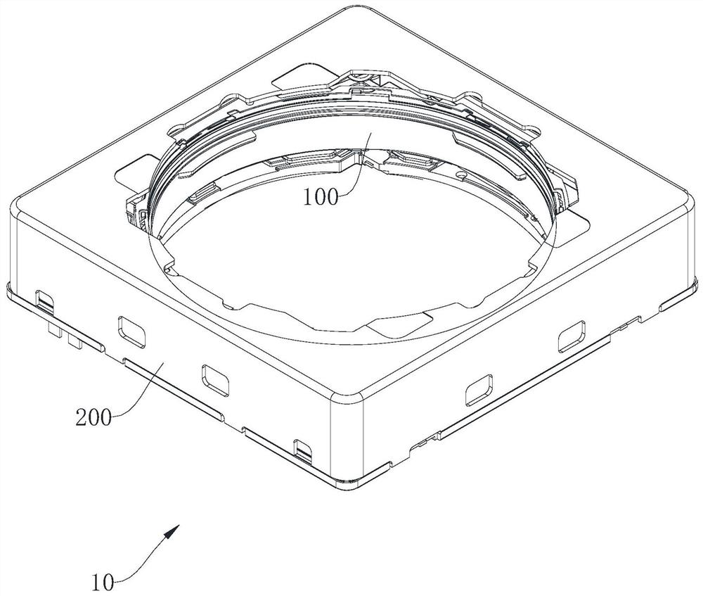
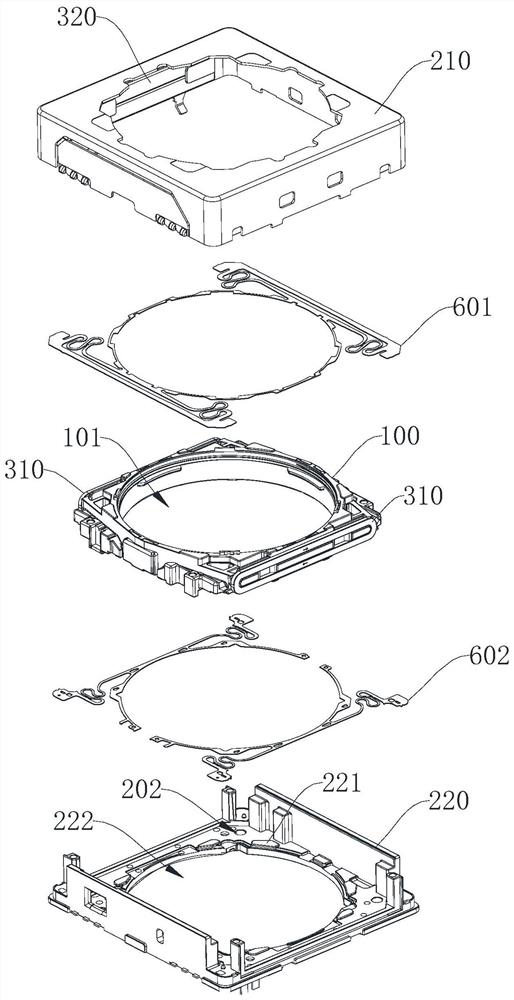
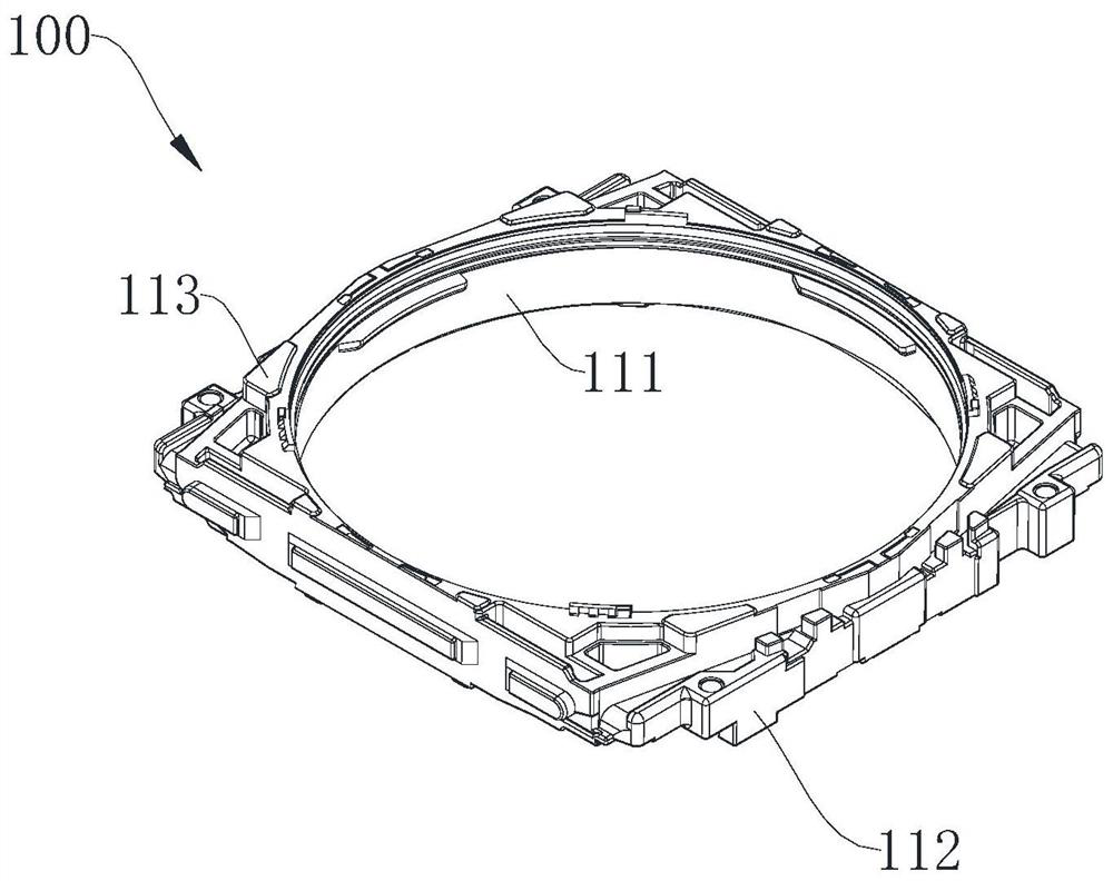
Motor and camera module

A camera module and motor technology, applied in windings, electric components, electromechanical devices, etc., can solve problems such as uneven surface, motor stains, and bad camera modules.

Active Publication Date: 2022-03-18
NINGBO SUNNY OPOTECH CO LTD
View PDF9 Cites 0 Cited by
  • Summary
  • Abstract
  • Description
  • Claims
  • Application Information

AI Technical Summary

Problems solved by technology

[0005] At present, the driving technology of the motor itself is relatively mature, but the problem of stains inside the motor has always troubled the manufacturer. The stains inside the motor may fall into structures such as the photosensitive chip, which will seriously affect the imaging quality of the camera module, and even cause It leads to defective camera modules, causing customer returns and other problems. According to statistics, the defective camera modules due to motor stains reach 10%
[0007] 1. During the production process of the motor, the components such as the casing, carrier or base of the motor are made by injection molding. After the injection molding is completed, the surface is not smooth, and there will be many burrs or dust. When these components are assembled into a motor structure, it may be The burrs or dust falling off the surface will be assembled inside the motor, forming motor stains. In addition, the dust in the production environment may also enter the interior of the motor with the assembly of the motor, forming motor stains
[0008] 2. During the motor inspection process, debris may be generated between the various parts of the motor due to collisions, forming motor stains
[0009] 3. During the transportation of the camera module, collisions will inevitably occur. At this time, the motor assembled in the camera module will also generate debris at the collision site, forming motor stains
[0010] 4. During the working process of the camera module, the dust in the external environment may also enter the motor from the gap of the motor structure, forming motor stains

Method used


Image

  • Motor and camera module
  • Motor and camera module
  • Motor and camera module

Examples


Embodiment Construction

[0053] Hereinafter, the present application will be further described in conjunction with specific implementation methods. It should be noted that, on the premise of not conflicting, the various embodiments or technical features described below can be combined arbitrarily to form new embodiments.

[0054] In the description of this application, it should be noted that for orientation words, such as the terms "center", "horizontal", "longitudinal", "length", "width", "thickness", "upper", "lower" , "Front", "Back", "Left", "Right", "Vertical", "Horizontal", "Top", "Bottom", "Inner", "Outer", "Clockwise", "Counterclockwise ” and other indication orientations and positional relationships are based on the orientations or positional relationships shown in the drawings, which are only for the convenience of describing the application and simplifying the description, rather than indicating or implying that the device or element referred to must have a specific orientation, use a speci...


PUM

PropertyMeasurementUnit
Widthaaaaaaaaaa

Abstract

The invention provides a motor and a camera module. The motor comprises a movable part, a fixed part and a driving mechanism, a movable cavity is defined by the fixed part, the movable part is movably installed in the movable cavity, the driving mechanism is used for driving the movable part to move in the movable cavity, and the motor further comprises at least one of a first feature, a second feature and a third feature. The first characteristic is that an elastic polymer layer is arranged on at least one part of the surface of the movable part and / or the fixed part so as to reduce direct contact between the movable parts; the second characteristic is that dust catching glue is arranged on at least one part of the surface of the movable component and / or the fixed component and used for catching particles in the movable cavity. The third characteristic is that the fixed part is provided with at least one dust removal through hole in the side wall limiting the movable cavity, so that when the openings in the two ends of the movable cavity are closed, the movable cavity can be communicated with the outside through the dust removal through hole. The motor for the camera module provided by the invention can effectively reduce the generation of motor stains.

Description

technical field [0001] This application relates to the technical field of camera modules, in particular to motors and camera modules. Background technique [0002] In the imaging process of the camera module, whether it is driving the lens to realize the focusing function or the anti-shake function, the driving component is an indispensable part of the high-pixel module. In general, the driving components in the mobile phone module are mainly motor structures, which are divided according to different driving methods. Basically, motors can be divided into suspension wire motors and SMA motors. [0003] The working principle of the suspension wire motor is: the motor structure includes a movable part (the lens is mounted on the movable part) and a fixed part, and a coil and a magnet structure are arranged at the relative position between the movable part and the fixed part. On the moving part, the magnet is set on the fixed part. When the current is passed through the coil, t...

Claims


Application Information

Patent Timeline
IPC IPC(8): H02K5/10H02K3/50G02B7/04G02B7/00
CPCH02K5/10H02K3/50G02B7/04G02B7/006
Inventor 何艳宁俞丝丝杨银凯方银丽李威刘傅文
Owner NINGBO SUNNY OPOTECH CO LTD
Learn More