
Cleaning head structure for cleaning equipment

A technology for cleaning equipment and cleaning heads, which is applied to cleaning equipment, cleaning devices, cleaning machinery, etc., and can solve problems such as unsatisfactory cleaning effect, impact on cleaning efficiency, and inability of sewage to be cleaned up in a timely and effective manner.

Pending Publication Date: 2022-03-22
WUHAN DIISEA INTLLIGENCE TECH CO LTD
View PDF5 Cites 2 Cited by
  • Summary
  • Abstract
  • Description
  • Claims
  • Application Information

AI Technical Summary

Problems solved by technology

However, the cleaned sewage on the drum cannot be cleaned up in time and effectively during the use process, so it is easy to leave stains on the cleaning surface during the cleaning process, resulting in unsatisfactory cleaning effect. It needs to be used many times, which also affects the cleaning efficiency. influences

Method used


Image

  • Cleaning head structure for cleaning equipment
  • Cleaning head structure for cleaning equipment
  • Cleaning head structure for cleaning equipment

Examples


Embodiment Construction

[0031] The claims of the present invention will be further described in detail below in conjunction with specific embodiments and accompanying drawings. Apparently, the described embodiments are only some of the embodiments of the present invention, not all of them. Based on the embodiments of the present invention, all other embodiments obtained by persons of ordinary skill in the art without creative work also fall within the protection scope of the present invention.

[0032] It should be understood that, in the descriptions of the embodiments of the present invention, all directional terms, such as "up", "down", "left", "right", "front", "rear", etc. indicate the orientation or position The relationship is based on the orientation and positional relationship shown in the drawings or the conventional orientation or positional relationship of the product of the invention in use, which is only for the convenience of simplifying the description of the present invention, rather ...


PUM


Abstract

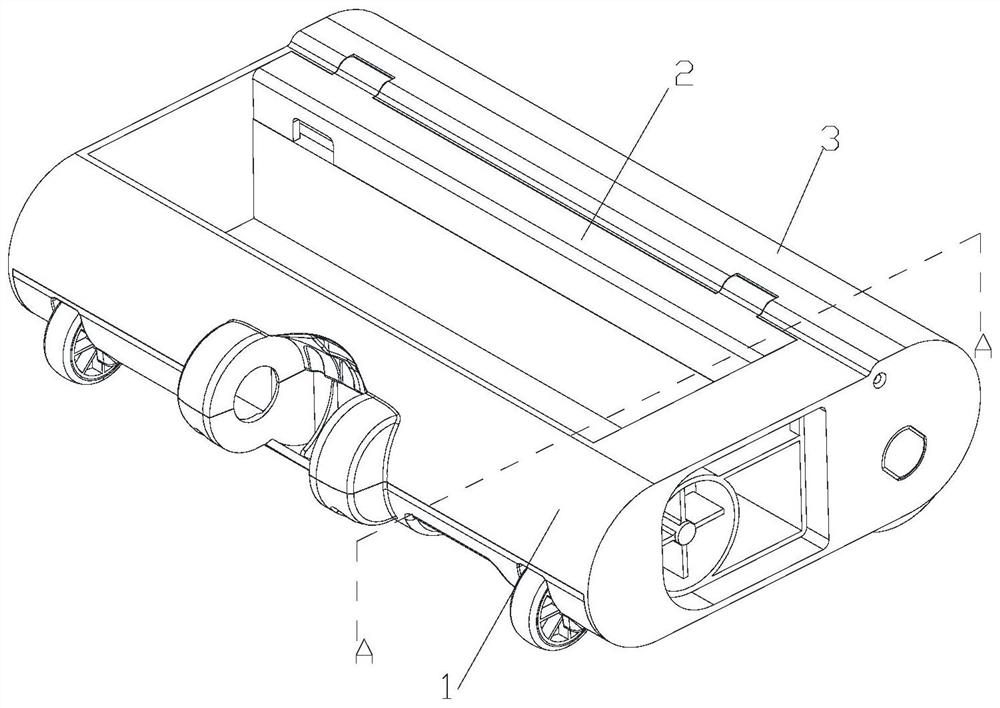
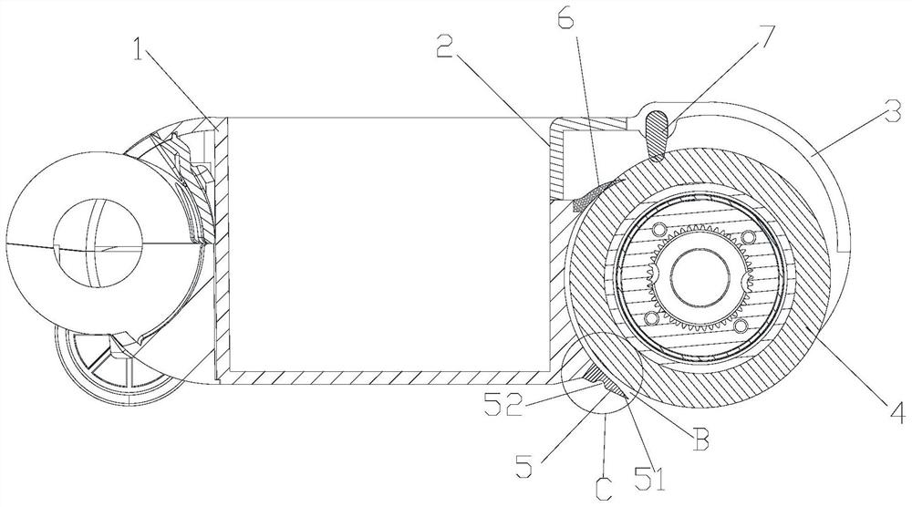
The invention is suitable for the technical field of cleaning appliances. The invention discloses a cleaning head structure for equipment, the cleaning head structure for the cleaning equipment comprises a cleaning head main body and a roller rotationally connected with the cleaning head main body, a water scraping mechanism is arranged between the cleaning head main body and the roller, and the water scraping mechanism is provided with a cleaning component for separating water scraped from the roller during cleaning. In the using process of the cleaning head structure for the cleaning equipment, due to the fact that the cleaning component can clean tiny solid or slender garbage from the roller before cleaning, the situation that when the roller is cleaned, even if the garbage can be cleaned, the garbage can be easily blocked in the cleaning water tank, and a water and dust cleaning flow path is affected is avoided. And the structure is simple and compact.

Description

technical field [0001] The invention relates to a cleaning device, in particular to a cleaning head structure for the cleaning device. Background technique [0002] The existing mopping and sweeping integrated sweeping device can realize most scenarios. However, the cleaned sewage on the drum cannot be cleaned up in time and effectively during the use process, so it is easy to leave stains on the cleaning surface during the cleaning process, resulting in unsatisfactory cleaning effect. It needs to be used many times, which also affects the cleaning efficiency. influences. Contents of the invention [0003] The technical problem mainly solved by the present invention is to provide a cleaning head structure for cleaning equipment, which can effectively prevent cleaning efficiency from being cleaned up in time because the cleaned sewage cannot be cleaned in time during the cleaning process, The structure is simple and compact. [0004] In order to solve the above problems,...

Claims


Application Information

Patent Timeline
IPC IPC(8): A47L11/282A47L11/24A47L11/40
CPCA47L11/282A47L11/24A47L11/4041A47L11/40A47L2201/00
Inventor 周杰万科学
Owner WUHAN DIISEA INTLLIGENCE TECH CO LTD
Learn More