Landscape gallery frame structure based on garden design

A landscape and gallery technology, applied in building structures, roofs using flat/curved panels, special buildings, etc., can solve the problems of inability to block rainwater, poor heat insulation, and inability to cool down, and increase entertainment. The effect of easy installation and disassembly

Pending Publication Date: 2022-03-22
上海阿特贝尔景观规划设计有限公司
View PDF5 Cites 1 Cited by
  • Summary
  • Abstract
  • Description
  • Claims
  • Application Information

AI Technical Summary

Problems solved by technology

[0003] However, when the current landscape gallery is used for people to use and rest, the top of the existing landscape gallery has poor heat insulation effect, especially in the case of high temperature in summer, the temperature of the lower space of the landscape gallery is high, and the lower part

Method used


Image

  • Landscape gallery frame structure based on garden design
  • Landscape gallery frame structure based on garden design
  • Landscape gallery frame structure based on garden design

Examples


Embodiment 1

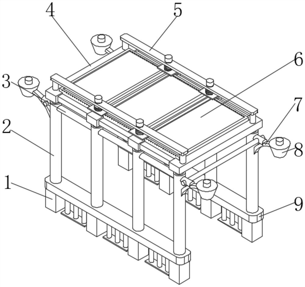
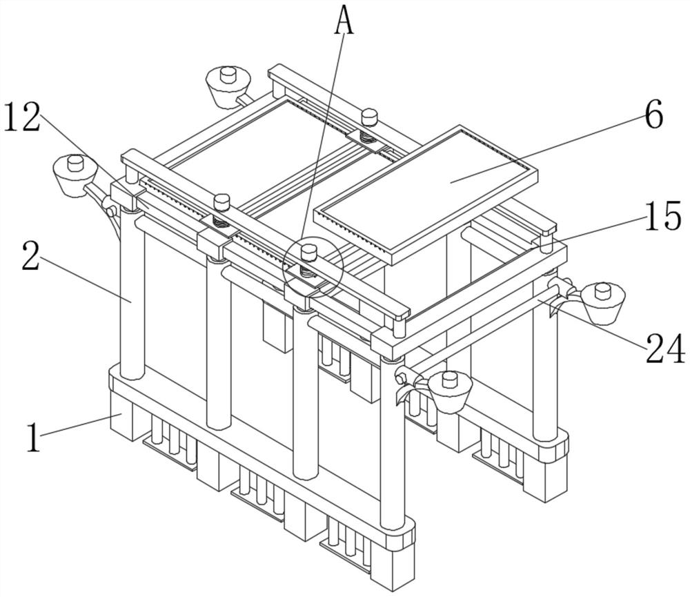
[0026] see Figure 1-5 , a landscape gallery structure based on garden design, including a base 1, two groups of bases 1, fixed columns 2 are fixedly installed above the two groups of bases 1, and support columns 11 are fixedly installed above the two groups of fixed columns 2 A plurality of top plates 4 are fixedly installed above the two sets of supporting columns 11, connecting columns 12 are fixedly installed on both sides of the top plate 4, and a plurality of placement grooves 15 are opened on the top plate 4, and gaskets are fixedly installed at the bottom of the placement grooves 15, and the gaskets are made of rubber Made, tempered glass 6 is placed on the inner side of each placement groove 15, a fixed frame 16 is fixedly installed around each toughened glass 6, and a sponge pad 18 is arranged around each fixed frame 16, and the sponge pad 18 and the placement groove 15 The inner walls are squeezed against each other, and several drain holes 17 are opened at both end...

Embodiment 2

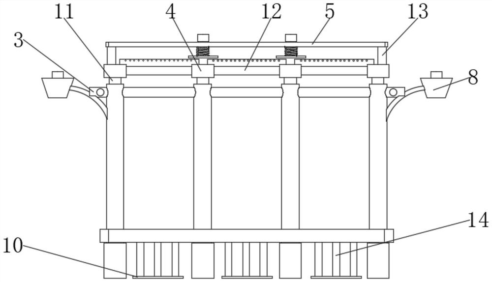
[0032] Based on Example 1, such as Figure 1-5 , the fastening mechanism includes a fixed rod 13, two sets of fixed rods 13 are fixedly installed on the top plates 4 at both ends, and a placement plate 5 is fixedly installed above the two groups of fixed rods 13, and several connecting holes 19 are provided above the two groups of placement plates 5 , each connecting hole 19 inside is plugged with a connecting rod 21, a fastening plate 23 is fixedly installed below the connecting rod 21, a fixed block 20 is fixedly installed on the top of the connecting rod 21, a telescopic spring 22 is arranged on the outside of the connecting rod 21, and the telescopic spring 22 The end is fixedly installed above the fastening plate 23, and the top of the fastening plate 23 is fixedly connected below the placement plate 5. When the tempered glass 6 is fixed, the operator first pulls the fixing block 20 upwards, so that the connecting rod 21 can be driven in the connecting hole 19. The inner ...


PUM


Abstract

The invention relates to the technical field of garden design, and discloses a garden design-based landscape gallery frame structure which comprises two bases, fixing columns are fixedly mounted above the two bases, supporting columns are fixedly mounted above the two fixing columns, a plurality of top plates are fixedly mounted above the two supporting columns, and connecting columns are fixedly mounted on the two sides of the top plates. A plurality of placing grooves are formed in the top plate. According to the landscape corridor frame structure based on the garden design, tempered glass is placed on the inner side of the containing groove above the top plate, when the tempered glass is used, the tempered glass can play a certain role in blocking rainwater and hot air irradiated by sunlight, drainage holes are formed in the two sides of the tempered glass, rainwater above the tempered glass is subjected to landscape drainage, and the practicability of the landscape corridor frame structure is improved. And meanwhile, the lighting lamps at the two ends of the landscape corridor frame can illuminate the whole landscape corridor frame, and the situation that due to the fact that light is dark at night, accidents happen when the tourists play is avoided.

Description

technical field [0001] The invention relates to the technical field of garden design, in particular to a landscape gallery structure based on garden design. Background technique [0002] Garden landscape chairs are often installed in landscape corridors in garden design for decoration. As the name implies, garden landscape chairs are benches and benches installed in gardens or parks for tourists and passers-by to rest. Garden landscape chairs are a kind of leisure chairs. . The scope of application of plastic-wood garden landscape chairs: cultural squares, parks, communities, streets, communities, municipal facilities, scenic spots and other areas. [0003] However, when the current landscape gallery is used for people to use and rest, the top of the existing landscape gallery has poor heat insulation effect, especially in the case of high temperature in summer, the temperature of the lower space of the landscape gallery is high, and the lower part of the landscape gallery ...

Claims


Application Information

Patent Timeline
IPC IPC(8): E04H1/12E04D3/06E04D13/04E04D3/36
CPCE04H1/1205E04D3/06E04D13/0404E04D3/3605
Inventor 刘春红苏林国
Owner 上海阿特贝尔景观规划设计有限公司
Why Eureka
Try Eureka