Multi-layer image display method and display engine
An image display and engine technology, which is applied in the directions of graphics and image conversion, image data processing, digital output to display devices, etc., can solve the problems of low efficiency and long time-consuming multi-layer image display, so as to reduce occupation, improve superimposed display efficiency, The effect of reducing the delay
- Summary
- Abstract
- Description
- Claims
- Application Information
AI Technical Summary
Problems solved by technology
Method used
Image

Examples
Embodiment 1
[0058] Such as figure 2 As shown, the multi-layer image display method in the present invention comprises the following steps:
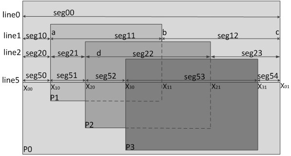
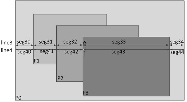
[0059] (1) Divide each pixel row into segments according to the display area of the uppermost layer in the unit of pixel row in the target image.
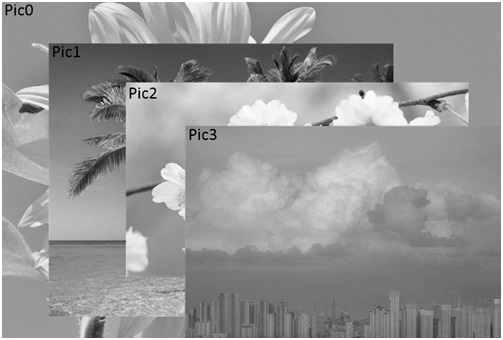
[0060] Such as image 3 As shown, the target image is composed of four images from P0 to P3, and the layers are numbered in order from the bottom layer to the upper layer. The layer where the P0 image is located is L0, the layer where the P1 image is located is L1, and the layer where the P2 image is located is The layer is L2; the layer where the P3 image is located is L3; the P0 image is located at the bottom layer of the target image, and some pixels are covered by the images of the layers above it; and some pixels of the P1 image located in the layer L1 are located on it The P2 image and P3 image of the layer are covered; except the P3 image located in the uppermost layer L3 is not covered, at ...
Embodiment approach
[0063] As an implementation of segment division, this implementation includes the following steps:
[0064] 1) Obtain the rendering layer at each pixel in units of pixel rows of the target image.
[0065] In the unit of pixel line, traverse each pixel point in turn, determine whether there is a pixel point of the corresponding layer at the pixel point by judging whether the pixel point is within the display range of a certain layer, and record the uppermost layer at the pixel point layer as a render layer. During specific implementation, when the target image is determined, its corresponding source image information and the zoomed image information corresponding to the source image can be easily obtained through software. The source image information includes: source image identification, source image size, and the zoomed image information includes: The size of the scaled image in the target image, the starting position of the scaled image in the target image, and the layer o...
Embodiment 2
[0106] According to the above description, when the target image is determined, its corresponding source image information and the zoomed image information corresponding to the source image can be easily obtained through software. On this basis, the horizontal step distance and vertical step distance can be further obtained. Determines the coincidence of the pixel matrix required for the fragment and the target pixel in the fragment group.
[0107]In Example 1, extracting data from the internal memory according to the pixel information of the source image required by the target pixel point is obviously an interval fetching data from the memory. However, the efficiency of interval fetching data from the memory is much lower than the efficiency of continuing to fetch data. If the source image mapping information of the segment is retrieved from the memory first, you only need to know the source image pixel information addresses corresponding to the first target pixel and the last...
PUM
 Abstract
Description
Claims
Application Information
 - R&D Engineer
- R&D Manager
- IP Professional
- Industry Leading Data Capabilities
- Powerful AI technology
- Patent DNA Extraction
Browse by: Latest US Patents, China's latest patents, Technical Efficacy Thesaurus, Application Domain, Technology Topic.
© 2024 PatSnap. All rights reserved.Legal|Privacy policy|Modern Slavery Act Transparency Statement|Sitemap