Supercharge Your Innovation With Domain-Expert AI Agents!

Aluminum beam top vertical rod connector

A technology of connectors and poles, applied in the field of connectors, can solve problems such as inconvenient use and inability to adjust, and achieve the effect of easy adjustment, easy fixing or loosening of items

Pending Publication Date: 2022-03-25
CHUZHOU JINCHENG METAL PROD CO LTD
View PDF10 Cites 1 Cited by
  • Summary
  • Abstract
  • Description
  • Claims
  • Application Information

AI Technical Summary

Problems solved by technology

[0003] The existing connecting head of the pole at the top of the aluminum beam, the connecting head and the connecting pipe are fixedly arranged, and the distance between the top of the connecting head and the top of the connecting pipe is fixed and cannot be adjusted, which is not convenient for use in different situations

Method used


Image

  • Aluminum beam top vertical rod connector
  • Aluminum beam top vertical rod connector
  • Aluminum beam top vertical rod connector

Examples


Embodiment 1

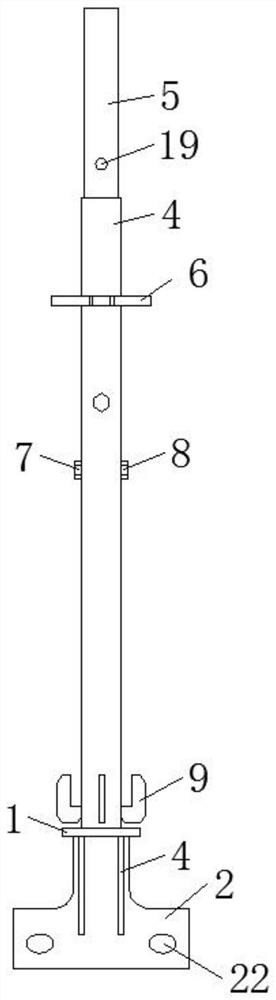
[0026] Such as Figure 1-5 As shown, a connecting head of a pole at the top of an aluminum beam includes a top plate 1, a side plate 2, a gusset plate 3, a connecting pipe 4, a connecting head 5, a circular connecting plate 6, a hexagonal bolt 7, a lock nut 8 and a fixing The plate 9, the side plate 2 is arranged at the bottom of the bottom plate 1, the connecting pipe 4 is arranged at the top of the top plate 1, the top of the gusset plate 3 is connected with the bottom of the top plate 1, the side wall of the gusset plate 3 is connected with the side plate 2, through the gusset plate 3 and The connection between the top plate 1 and the side plate 2 is more stable, the circular connecting plate 6 is sleeved on the outer wall of the connecting pipe 4, the fixed plate 9 is connected to the bottom of the outer wall of the connecting pipe 4, the connecting head 5 is movable in the connecting pipe 4, and the inner side of the connecting pipe 4 The top of the wall is provided with ...

Embodiment 2

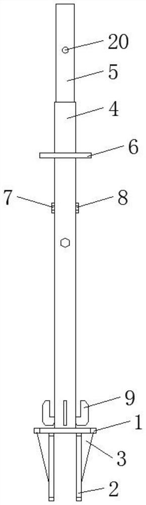
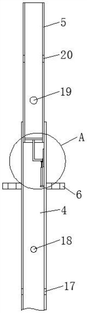
[0029] Such as figure 1 , Figure 6 As shown, a connecting head of a pole at the top of an aluminum beam includes a top plate 1, a side plate 2, a gusset plate 3, a connecting pipe 4, a connecting head 5, a circular connecting plate 6, a hexagonal bolt 7, a lock nut 8 and a fixing Plate 9, side plate 2 is set at the bottom of bottom plate 1, connecting pipe 4 is set at the top of top plate 1, the top of gusset plate 3 is connected to the bottom of top plate 1, the side wall of gusset plate 3 is connected to side plate 2, and 6 sets of circular connecting plates Located on the outer wall of the connecting pipe 4, the fixing plate 9 is connected to the bottom of the outer wall of the connecting pipe 4, the connecting head 5 is movably arranged in the connecting pipe 4, and the outer wall of the connecting pipe 4 is provided with a strip-shaped through hole 23 on the side close to the fixing plate 9, and the connecting pipe 4 is provided with the disk 24 of movable connection, a...


PUM


Abstract

The invention discloses an aluminum beam top vertical rod connector which comprises a top plate, a side plate, an angle supporting plate, a connecting pipe, a connector body, a circular connecting plate, a hexagon bolt, a locking nut and a fixing plate, the circular connecting plate is arranged on the outer wall of the connecting pipe in a sleeving mode, the fixing plate is connected with the bottom of the outer wall of the connecting pipe, and the connector body is movably arranged in the connecting pipe. A sliding plate is arranged in the sliding rail in a matched mode, an L-shaped connecting rod and a second connecting block are arranged on the side wall of the sliding plate, a first electric push rod is arranged at the bottom of the second connecting block, one end of the first electric push rod is connected with the top of the first connecting block, and a supporting plate is arranged on the inner wall of the connector; one end of the L-shaped connecting rod is connected with the bottom of the supporting plate. The vertical rod connector is convenient and fast to use, the connector can be driven to move up and down relative to the connecting pipe, the distance between the connector and the connecting pipe can be conveniently adjusted, and the vertical rod connector can be conveniently used under different conditions.

Description

technical field [0001] The invention relates to the technical field of connectors, in particular to a rod connector at the top of an aluminum beam. Background technique [0002] The aluminum beam occupies a very important position in the integrated ceiling. From the name of the aluminum beam, we can know that it is an aluminum alloy material. The meaning of the beam is that the beam can be divided into: rectangular section beam, T-shaped section beam, cross-section beam, I-shaped section beam, Yi-shaped section beam, mouth-shaped section beam, and irregular section beam according to the section form. The combination of aluminum and beam is an irregular cross-section beam made of aluminum alloy. It is the core material of the secondary ceiling commonly used in integrated ceilings. Aluminum beams are structurally divided into: integrated beams and composite beams. We can know from the name that the integrated beam is an aluminum beam whose cross section is integrated (that ...

Claims


Application Information

Patent Timeline
IPC IPC(8): E04B9/20
CPCE04B9/20
Inventor 张传金张虎林辉李帮福黄艳丽杨玉浩
Owner CHUZHOU JINCHENG METAL PROD CO LTD
Features
  • R&D
  • Intellectual Property
  • Life Sciences
  • Materials
  • Tech Scout
  • Unparalleled Data Quality
  • Higher Quality Content
  • 60% Fewer Hallucinations
Learn More