
Control method and device of magnetic suspension bearing, magnetic suspension system and storage medium

A technology of a magnetic suspension bearing and a control method, applied in the field of magnetic suspension, can solve the problems of unsuitable magnetic suspension compressors, consistent parameters of magnetic suspension compressors, suspension failure, etc., and achieve the effects of improving the reliability of rotor suspension and improving the accuracy of rotor suspension.

Active Publication Date: 2022-03-25
GREE ELECTRIC APPLIANCES INC
View PDF16 Cites 3 Cited by
  • Summary
  • Abstract
  • Description
  • Claims
  • Application Information

AI Technical Summary

Problems solved by technology

[0004] The object of the present invention is to provide a control method, device, magnetic levitation system and storage medium of a magnetic levitation bearing, to solve the problem that in the magnetic levitation system, the same type of magnetic levitation compressors usually adopt the same PID control parameters, but due to the It is not guaranteed that the parameters of the same type of magnetic levitation compressors are exactly the same, which will cause the same set of PID control parameters to not apply to all the same type of magnetic levitation compressors, resulting in a mismatch of PID control parameters, and even cause the rotor of the magnetic levitation bearing to levitate For the problem of poor precision or suspension failure, the automatic matching of the PID control parameters of the magnetic suspension compressor can improve the suspension accuracy of the rotor of the magnetic suspension bearing and improve the reliability of the rotor suspension of the magnetic suspension bearing.

Method used


Image

  • Control method and device of magnetic suspension bearing, magnetic suspension system and storage medium
  • Control method and device of magnetic suspension bearing, magnetic suspension system and storage medium
  • Control method and device of magnetic suspension bearing, magnetic suspension system and storage medium

Examples


Embodiment Construction

[0037] In order to make the purpose, technical solution and advantages of the present invention clearer, the technical solution of the present invention will be clearly and completely described below in conjunction with specific embodiments of the present invention and corresponding drawings. Apparently, the described embodiments are only some of the embodiments of the present invention, but not all of them. Based on the embodiments of the present invention, all other embodiments obtained by persons of ordinary skill in the art without making creative efforts belong to the protection scope of the present invention.

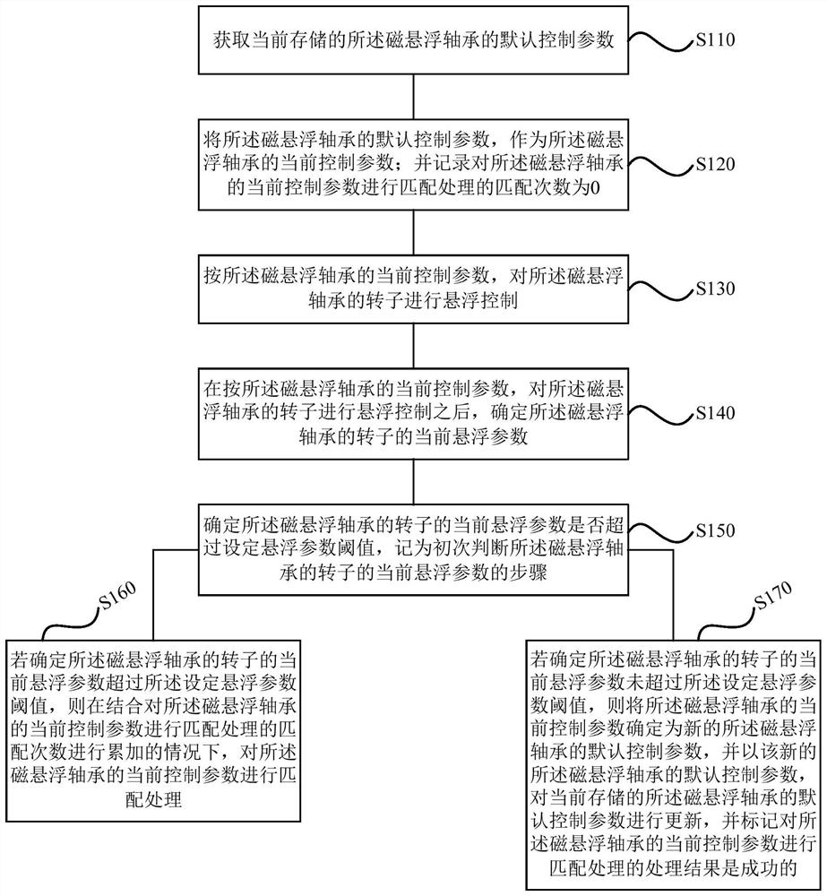
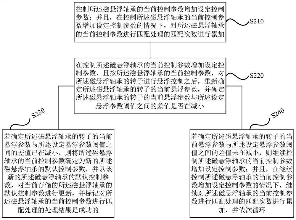
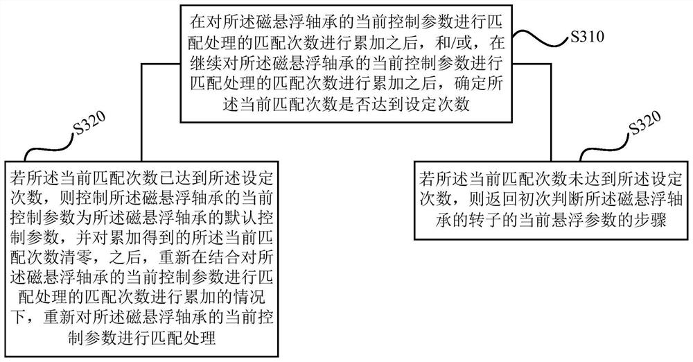
[0038] According to an embodiment of the present invention, a method for controlling a magnetic suspension bearing is provided, such as figure 1 A schematic flow diagram of an embodiment of the method of the present invention is shown. The control method of the magnetic suspension bearing may include: step S110 to step S170.

[0039] At step S110, the currently ...


PUM


Abstract

The invention discloses a control method and device for a magnetic suspension bearing, a magnetic suspension system and a storage medium, and the method comprises the steps: obtaining a currently stored default control parameter of the magnetic suspension bearing, taking the default control parameter as a current control parameter, and recording the matching frequency as 0; the rotor is controlled according to the current control parameter, and then whether the current suspension parameter of the rotor exceeds a set suspension parameter threshold value or not is determined; if yes, matching processing is carried out on the current control parameters under the condition that the number of matching times is accumulated; and if not, determining the current control parameter as a new default control parameter, updating the currently stored default control parameter by using the new default control parameter of the magnetic suspension bearing, and marking that the matching processing is successful. According to the scheme, by automatically matching the PID control parameters of the magnetic suspension compressor, the rotor suspension precision of the magnetic suspension bearing can be improved, and the rotor suspension reliability of the magnetic suspension bearing can be improved.

Description

technical field [0001] The invention belongs to the technical field of magnetic suspension, and in particular relates to a control method, a device, a magnetic suspension system and a storage medium of a magnetic suspension bearing. Background technique [0002] Most of the magnetic suspension bearings adopt the classic PID (proportional-integral-derivative) control method, and adjusting the PID control parameters can realize the stable suspension of the rotor. In maglev compressors, the same type of maglev compressors usually use the same PID control parameters, but because the actual assembly and production cannot guarantee that the maglev compressors are completely consistent, this may cause the same set of PID parameters to not apply to all maglev compressors , the PID parameters do not match, and even lead to poor levitation accuracy of the rotor or levitation failure. [0003] The above content is only used to assist in understanding the technical solution of the pres...

Claims


Application Information

Patent Timeline
Patent Type & Authority Applications(China)
IPC IPC(8): F16C32/04G05B11/42
CPCF16C32/0451G05B11/42
Inventor 赵科杰张伦生陈澍国陈灿枫
Owner GREE ELECTRIC APPLIANCES INC
Learn More