
Energy-saving industrial cold and hot integrated water chilling unit

An integrated technology for water chillers, applied in the direction of refrigerators, refrigeration components, mechanical equipment, etc., can solve the problems of large storage space, low refrigerant content, and cost, so as to improve efficiency, reduce use time, increase The effect of large contact area

Active Publication Date: 2022-03-25
恩德特机械(苏州)有限公司
View PDF5 Cites 0 Cited by
  • Summary
  • Abstract
  • Description
  • Claims
  • Application Information

AI Technical Summary

Problems solved by technology

[0002] The existing industrial cold and hot water chillers occupy a large space and are inconvenient. During the cooling and heating cycle, the refrigerant vapor inside the evaporator is directly extracted by the compressor into the condenser, and then refluxed again as in the evaporator. heat absorption in chilled water
Among them, due to the fact that the heat of chilled water is not stable in reality, the refrigerant content in the existing chillers is relatively fixed from the initial amount, resulting in uneven steam concentration after the refrigerant absorbs the heat of chilled water, resulting in the occurrence of chilled water The heat is too high, which in turn reflects that the refrigerant content is low, resulting in the refrigerant failing to reach the optimal steam concentration after each cycle, so that the heat absorbed by each cycle is less, thereby increasing the operating power of the compressor. If the chilled water If the heat is too low, the refrigerant will even liquefy on a large scale, resulting in poor circulation with the refrigerant and uneven heat absorption, which will consume a lot of energy

Method used


Image

  • Energy-saving industrial cold and hot integrated water chilling unit
  • Energy-saving industrial cold and hot integrated water chilling unit
  • Energy-saving industrial cold and hot integrated water chilling unit

Examples


Embodiment Construction

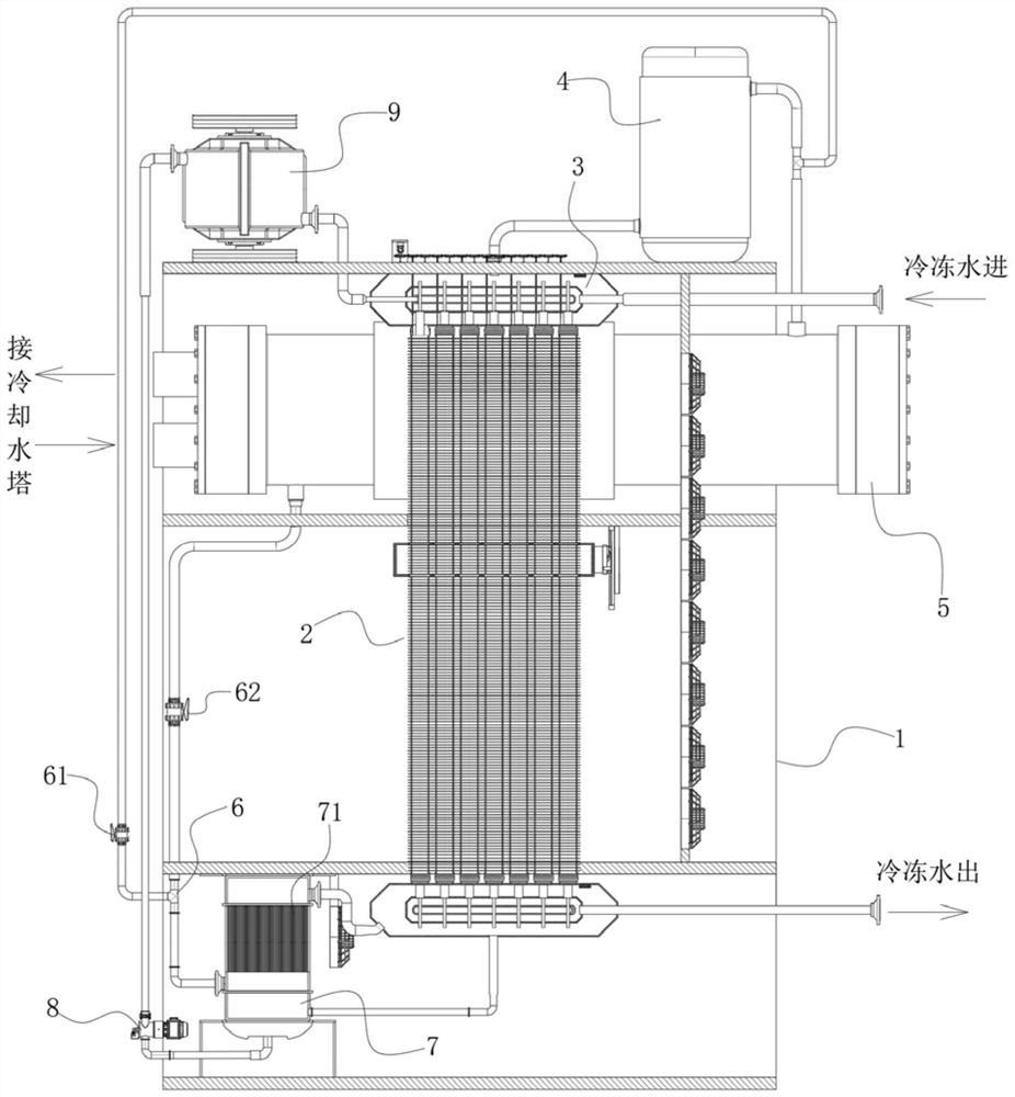
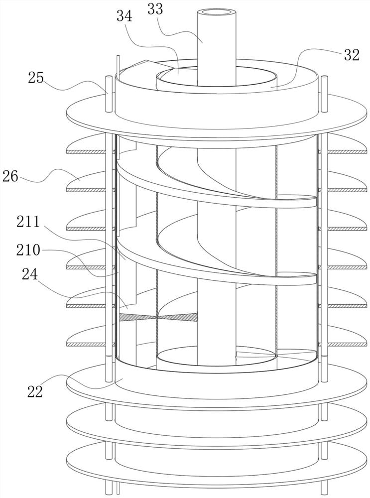
[0033] refer to Figure 1-5 , the present invention provides a technical solution: an energy-saving industrial cooling and heating integrated chiller, which includes a fixed plate frame 1, a flow control box 7 is installed on the bottom of the fixed plate 1, and a horizontally arranged condenser is installed on the top. Regulator tank 9 and compressor 4 are installed on the upper part of device 5, the top end, and outer drainage shell 2 arranged longitudinally is installed in the middle of the fixed plate frame, and inner diversion assembly 3 is embedded inside the outer drainage shell 2, and the The input end and the output end of the compressor 4 are respectively connected to the upper output end of the external drainage shell 2 and the upper right input end of the condenser 5, and the lower left output end of the condenser 5 is connected to the upper port of the three-communication 6 pipe, and is controlled by the The valve two 62 is regulated, and the output end of the com...


PUM


Abstract

The energy-saving industrial cold and hot integrated water chilling unit comprises a fixing plate frame, a flow adjusting box is installed on the portion, close to the bottom, of the fixing plate frame, a transversely-arranged condenser is installed on the portion, close to the top, of the fixing plate frame, a regulation and control tank and a compressor are installed on the upper portion of the top end of the fixing plate frame, and a longitudinally-arranged outer drainage shell is installed in the middle of the fixing plate frame; an inner flow guide assembly is embedded in the outer flow guide shell, the input end and the output end of the compressor are connected with the upper output end of the outer flow guide shell and the input end of the right upper side of the condenser through pipelines correspondingly, and the output end of the left lower side of the condenser is connected with an upper port of a three-way joint through a pipeline and is regulated and controlled through a second control valve. The output end of the compressor is in pipeline connection with left ports of the three communicating pipes and is regulated and controlled by the first control valve, lower ports of the three communicating pipes are in pipeline connection with the leading-in end of the lower left side of the flow regulating box, and the output end of the lower right side of the regulating and controlling tank is in pipeline connection with the inner flow guiding assembly.

Description

technical field [0001] The invention relates to the technical field of industrial cooling and heating chillers, in particular to an energy-saving industrial cooling and heating integrated chiller. Background technique [0002] The existing industrial cold and hot water chillers occupy a large space and are inconvenient. During the cooling and heating cycle, the refrigerant vapor inside the evaporator is directly extracted by the compressor into the condenser, and then refluxed again such as the evaporator Heat absorption of chilled water. Among them, due to the fact that the heat of chilled water is not stable in practice, the refrigerant content in existing chillers is relatively constant from the initial amount, resulting in uneven steam concentration after the refrigerant absorbs the heat of chilled water, resulting in the occurrence of chilled water The heat is too high, which in turn reflects that the refrigerant content is low, resulting in the refrigerant failing to ...

Claims


Application Information

Patent Timeline
Patent Type & Authority Applications(China)
IPC IPC(8): F25B41/40
CPCF25B41/40F25B2500/12
Inventor 胡兵
Owner 恩德特机械(苏州)有限公司
Learn More